Micheal_Leo
- 103
- 4
- TL;DR
- Instrumentation Amplifier
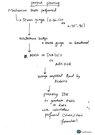
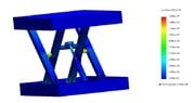
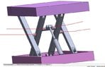
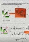
I am going to do some experiment on mechanical mechanism , studying stresses
Thing that in my mind
Arduino
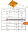
Strain gauge
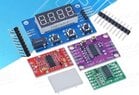
Instrumentation amplifier
I want to know that which Instrumentation amplifier i should use to get good output voltage from wheatstone bridge circuit and also easy to use
Thank you very much
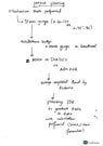
Thing that in my mind
Arduino
Strain gauge
Instrumentation amplifier
I want to know that which Instrumentation amplifier i should use to get good output voltage from wheatstone bridge circuit and also easy to use
Thank you very much