lorenz0
- 151
- 28
- Homework Statement
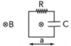
- A square circuit of side ##a=10cm## with a resistance ##R=1k\Omega## and a capacitor ##C=100nF## is in a region of space where there is a ##\vec{B}## field perpendicular to circuit, pointing inward, which changes according to ##\frac{dB}{dt}=-0.01 T/s##
Find the maximum charge on the plates of the capacitor and which plate is going to be positively charged and which one is going to be negatively charged.
- Relevant Equations
- ##\oint_{\Gamma}\vec{E}\cdot d\vec{l}=-\frac{d\phi(\vec{B})}{dt}##
What I have done:
The electromotive force due to Faraday's Law is: ##\mathcal{E}=-\frac{d\phi(\vec{B})}{dt}=\frac{d}{dt}(Ba^2)=a^2\frac{dB}{dt}=-10^{-4}V.##
In the circuit, going around the loop in a clockwise fashion:
##\oint_{\Gamma}\vec{E}\cdot d\vec{l}=-\frac{d\phi(\vec{B})}{dt}\Rightarrow iR+\frac{q}{C}=\mathcal{E}\Rightarrow \frac{dq}{dt}R+\frac{q}{C}=\mathcal{E}\Rightarrow \frac{dq}{dt}=-\frac{q-C\mathcal{E}}{RC}##
##\Rightarrow \int_{0}^{q}\frac{d\bar{q}}{\bar{q}-C\mathcal{E}}=-\int_{0}^{t}\frac{d\bar{t}}{RC}\Rightarrow [\ln(\bar{q}-C\mathcal{E})]_{0}^{q}=-\frac{t}{RC}\Rightarrow \ln\left(-\frac{q}{C\mathcal{E}}+1\right)=-\frac{t}{RC}\Rightarrow q(t)=C\mathcal{E}(1-e^{-\frac{t}{RC}})## so ##q_{max}=C\mathcal{E}=\left(100\cdot 10^{-9}\cdot (-10^{-4})\right) C=-10^{-11} C##.
Since the current goes around in a clockwise fashion, the upper plate should be charge positively and the bottom one negatively.
Now, I have a doubt: does it make sense that ##q_{max}## comes out negative?
Other than that, is my solution correct? Thanks
Attachments
Last edited: