Discussion Overview
The discussion revolves around the behavior of an LC circuit, specifically why it does not oscillate energy between electric and magnetic fields as expected. Participants explore various aspects of the circuit's design, components, and measurement techniques, addressing theoretical and practical considerations.
Discussion Character
- Exploratory
- Technical explanation
- Debate/contested
- Mathematical reasoning
Main Points Raised
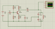
- The original poster (OP) describes their LC circuit setup, including the inductor and capacitor specifications, and notes that the circuit does not oscillate as expected after the initial discharge.
- Some participants inquire about the inductance and series resistance of the circuit, suggesting these factors could influence oscillation frequency and duration.
- Concerns are raised about the capability of standard multimeters to detect oscillations, with suggestions to use an oscilloscope for better measurement accuracy.
- Participants discuss the timing between removing the power source and measuring the circuit, questioning how this might affect observations.
- One participant proposes increasing the number of turns on the inductor to lower the resonant frequency into the AM broadcast band, potentially making oscillations detectable.
- Another suggests using a timer integrated circuit and a transistor to maintain oscillations by switching the DC voltage on and off.
- There are mentions of superconductors potentially sustaining oscillations indefinitely, but also the idea that energy loss through radiation could prevent perpetual oscillation.
- Some participants emphasize the need for specific measurement tools, like oscilloscopes or AM radios, to effectively observe the oscillations.
- Discussions include the original resonant frequency calculations and the implications of changing circuit components to achieve desired oscillation behavior.
Areas of Agreement / Disagreement
Participants express a range of views on the factors affecting oscillation in the LC circuit, with no consensus reached on a definitive solution. There is agreement that standard multimeters may not be suitable for detecting oscillations, but differing opinions on the necessary modifications to the circuit and the role of various components remain unresolved.
Contextual Notes
Limitations include the potential inaccuracies in measurements due to the choice of instruments, assumptions about component behavior, and the dependence on specific circuit configurations. The discussion does not resolve the mathematical steps involved in calculating resonant frequencies or the effects of component changes.
Who May Find This Useful
This discussion may be of interest to individuals exploring LC circuits, those interested in experimental physics, and participants looking to understand the nuances of oscillation behavior in electrical circuits.