Patrick Herp
- 5
- 0
- Homework Statement
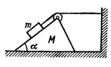
- The figure shows a block of mass m above a prism of mass M with a slope α. The block is connected to the wall through a massless rope and pulley system. Assume all surfaces are smooth. Determine the acceleration of prism M with respect to the ground.
- Relevant Equations
- $$
\sum{F} = ma
$$
The figure shows a block of mass m above a prism of mass M with a slope α. The block is connected to the wall through a massless rope and pulley system. Assume all surfaces are smooth. Determine the acceleration of prism M with respect to the ground.
(Figure is the last attached image)
I can draw the force diagram on block m like the first attached image, but I'm not sure about my force diagram for prism M (second attached image). If that's true, then I think the prism acceleration should be:
$$
a_x = \frac{F_x}{M} = \frac{mg \sin{\alpha} \cos{\alpha}}{M} = \frac{m}{M} g\sin{\alpha} \cos{\alpha}
$$
The thing is, I don't know how to justify my force diagram on the prism. Is the contact force on the prism from the block really ## mg \sin{\alpha} \cos{\alpha} ##?