MDG
- 8
- 0
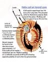
I built this DIY generator on the thought that the flux from two north poles of a magnet would be attracted to an iron core of a toroid coil. I wrapped the 4 inch OD toroidal coil with about 700 turns of 27 awg wire. The toroid coil is stationary with the magnetic flux rotating around the coil. I've only been able to produce about 500 millivolts with it being very erratic. DC in one direction for 1 second then the other direction for a second or two. Switched the voltmeter over to AC and I get a reading of 400 to 500 millivolts. I don't know why it doesn't work. According to "Fleming's right hand rule" it should...but doesn't. I'm attaching a simple drawing showing the principal of it. I must be violating some law of physics so if anybody here could point it out I would appreciate it. It's driving me crazy.