- #36
piepermd
- 51
- 2
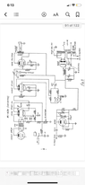
Yes, I’m using the Si5351 chip for thatBaluncore said:It looks to me like it has RF tuning only on RX, but has two separate switched four channel crystal oscillators, one for TX, the other for RX. It should be possible to replace the crystal oscillator(s) with digital synthesizer board(s). The harmonic multipliers that generate the TX carrier, and the LO for RX, can still be used.
There should be no problem using varactors to tune the small RF signals in the RX path, but you can expect problems generating the higher amplitude RF needed to replace the crystal oscillators. For those, you should look at synthesizer ICs that include a current controlled CMOS oscillator inside a PLL.