2025 Award
- 17,118
- 10,627
What is the purpose of the 220k resistors from the op-amp's low-Z output to both supply rails ?
Svein said:From your measurements, something is wrong around TIP112/TIP126. The emitter voltage should be -1.18V (the mirror image at the emitter of TIP117).
Baluncore said:What is the purpose of the 220k resistors from the op-amp's low-Z output to both supply rails ?
meBigGuy said:I can easily see how it works as class B.
Nobody has actually answered by basic question. I'll ask the question another way. When the output voltage is exactly 0, what significant, controllable, current flows through the PNP and NPN final transistor's collectors to make it class AB (and not just a sloppy class B). And what, EXACTLY, sets that current?
Nor did I.Jeff Rosenbury said:You are correct. I didn't check the data sheets on the biasing transistors.
That makes them properly biased.
meBigGuy said:When the output voltage is exactly 0, what significant, controllable, current flows through the PNP and NPN final transistor's collectors to make it class AB (and not just a sloppy class B). And what, EXACTLY, sets that current?
That is a stretch. The drivers are directly coupled emitter followers. That's it. If you want to consider that emitter followers operate in this manner then I guess that's that. You can say the same thing with a pair of diodes used to bias the outputs. Whatever is driving a pair of diodes being used for biasing is 'stealing current' from the outputs' bases as well.Svein said:Now I see one weakness with the construction. The driver transistors do not drive the output transistors, they work by stealing bias current from them.
Svein said: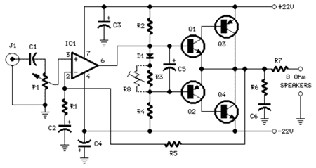
In that example, Q1 with Q3 and Q2 with Q4 form three terminal Complementary Darlington or Sziklai pairs.Svein said:Here is an example of a similar audio amplifier. Observe that the current is amplified through the driver stage, not shared.
jim hardy said:with zero offset in the opamp,
I = (Vbe of biasing transistor - Vbe of final transistor )/ 0.33Ω ?
It has already been answered:Averagesupernova said:Actually, no it is not amplified in what you call the driver stage since in order for the emitter of Q1 and Q2 to source this current it has to come through the base of Q3. This current won't be a whole heckuva lot.
Baluncore said:In that example, Q1 with Q3 and Q2 with Q4 form three terminal Complementary Darlington or Sziklai pairs.
Complementary Darlington transistors have lower base emitter voltages than the standard Darlington configuration that uses transistors of the same polarity. That is because saturation can allow the VBE of the two elements to overlap.
https://en.wikipedia.org/wiki/Sziklai_pair
meBigGuy said:what determines the difference between the Vbe of those two transistors?
meBigGuy said:HOORAY --- A coherent answer. And, given that answer, what determines the difference between the Vbe of those two transistors? Maybe the bias resistors have some effect. Certainly does not seem like a robust design with respect to class AB quiescent final stage current. I consider it a sloppy class B design. Some will work well, some not so well. Depends on Vbe matching of discrete devices.
As for the 220K resistors, I don't can't assign a purpose to those either.
Another quality of design issue is that the opamp is not sourcing current at 0V. I generally add a load resistor from the opamp output to the negative supply to keep the output transistor conducting. Helps with crossover distortion.
The lack of bypass on the feedback resistor has been mentioned before.
I don't have an answer for why lowering the bias resistors to 1.5K made the sound poor. I'd have to see the waveform. These transistors have internal resistors that are not on your schematic. Maybe that is part of it. ( see fig 1 in http://www.onsemi.com/pub_link/Collateral/TIP120-D.PDF )
Svein said:
- Since there is almost no local feedback, only an overall feedback, I see a possible problem with TIM (Transient Intermodulation Distortion).
rude man said:I would test trasient response with a square-wave drive to look at the leading & lagging edges.
meBigGuy said:Am I completely out of whack here? Is it a class B or a class AB?
jim hardy said:Quiescent readings across the 0.33 ohm resistors would say which it is at the moment.
I suspect that'll change with temperature, especially if driver and output transistors aren't real close together on the heatsink.