Help understanding this asynchronous sequential circuit please

  • Context: Engineering 
  • Thread starter Thread starter momentum
  • Start date Start date
  • Tags Tags
    Asynchronous Circuit
Join the discussion
Ask a follow-up here, or get your own question answered by working scientists, mathematicians and engineers — people, not an autocomplete.
Real named experts · corrections over time · the nuance an AI answer skips
12 replies · 2K views
momentum
Messages
111
Reaction score
0
Homework Statement
fundamental mode circuit
Relevant Equations
NA
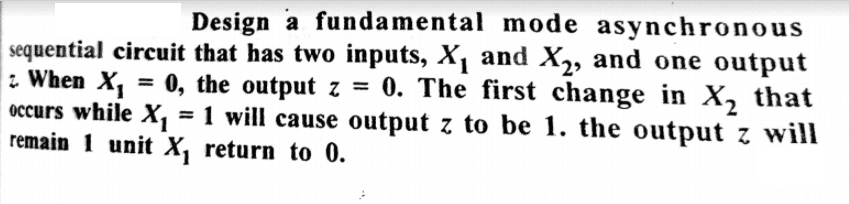
I am finding difficulty in understanding the sequence transition graph
EGpCtQv.png


My Book has given solution like this

cLw4UUM.png


Question : I have marked red circle in the above table. ...book has given E but I think it should be F ...What is correct here E or F ?

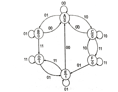
Here is the state diagram given in the book
P2oqvJ4.png
 
Last edited:
Physics news on Phys.org
I don't see how statement #2 can be simplified. It is a very straight-forward description of sequential behavior.

Perhaps you are confused because one can't do a simple truth table for states in sequential transitions. Those are for static circuits where sequencing doesn't enter into it. In this case you'll have to draw waveforms (squarewaves) showing the various possible states.
 
phinds said:
It is a very straight-forward description of sequential behavior.

I have edited my question and defined the problem area now. Could you please take a look at it again ?
 
momentum said:
I have edited my question and defined the problem area now. Could you please take a look at it again ?
And do what?

EDIT: Oh, sorry. I see there IS a question in there.
 
phinds said:
And do what?

I have marked red circle in the above table. ...book has given E but I think it should be F ...What is correct here E or F ?
 
phinds said:
I don't see any definition of what those "present state" letters stand for
A,B,C etc...these are just usual transitions states.
 
momentum said:
A,B,C etc...these are just usual transitions states.
Sorry, I don't have no idea what that means, "usual transition" states. How are they defined? What, for example, is "present state C" ?
 
phinds said:
Sorry, I don't have no idea what that means, "usual transition" states.

No problem. I'll figure out the solution. thanks
 
Last edited:
Yes, there are conflicts between the state diagram and the state transition table. It looks like they are for different problems?
 
  • Like
Likes   Reactions: berkeman
DaveE said:
Yes, there are conflicts between the state diagram and the state transition table. It looks like they are for different problems?

I suspect that this is a printing mistake in state transition table. Can you please confirm this ?

my book shows E (red circle) in the table but I think it should be F ( as per the state diagram).

I am fine with the state transition diagram.

It seems book has printed mistakenly E ( instead of F) in the table... right ?
 
momentum said:
I suspect that this is a printing mistake in state transition table. Can you please confirm this ?

my book shows E (red circle) in the table but I think it should be F ( as per the state diagram).

I am fine with the state transition diagram.

It seems book has printed mistakenly E ( instead of F) in the table... right ?
I suppose yes, but there are other discrepancies in addition to that. I'm not too motivated to find all of the errors. Frankly it is easier to just make the correct table from the diagram (or vice-versa) than it is to analyze how someone else did it wrong.

What I haven't done is match either the diagram or the table up to the words, I suspect that would be the best approach. You have three descriptions of the system, and I know two don't agree.
 
The table shows direct transitions C→E, D→C, E→C, F→A, and F→D. None of these are shown in the state diagram.

I guess "-,-" in the table means you are suppose to fill those in? Otherwise, I don't understand that notation.