Rindler Motion in Special Relativity: Rindler Coordinates
Table of Contents
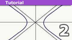
Our destination
In our last article, Hyperbolic Trajectories, we derived some facts about the trajectory of a rocket that is undergoing constant (proper) acceleration. In this article, we will explore what these facts mean for the passengers on board a rocket undergoing Rindler motion. The goal is to come up with a coordinate system that will be convenient to use by the passengers. Because the rocket does not stay at rest (except momentarily) in any inertial reference frame, the onboard coordinate system will necessarily be noninertial. However, for the passengers themselves, it will not be too weird–they should still be able to determine locations within the rocket using the meter sticks that they have available, and they should be able to still have a time coordinate that can be used to plan meetings and so forth within the rocket.
Before getting to that coordinate system, I’m going to take a sort of long-winded path. The point of the detour is to motivate that coordinate system, to show that it really is the most convenient one to be used by our rocket travelers.
Recap of the last article
In the last article, Hyperbolic Trajectories, we derived some facts about the trajectory of a rocket that is undergoing constant (proper) acceleration. Let me repeat a few of the formulas we derived:
Equation 1: ##x = x(0) + \frac{c}{g}(V^0 – V^0(0))##
Equation 2: ##ct = ct(0) + \frac{c}{g} (V^1 – V^1(0)) ##
Equation 3: ##x = \sqrt{c^2 t^2 + \frac{c^4}{g^2}}##
Equation 4: ##\frac{d V^0}{d\tau} = \frac{g}{c} V^1##
Equation 5: ##\frac{d V^1}{d\tau} = \frac{g}{c} V^0##
In these equations, ##g## is the acceleration of the rocket, ##x## is the spatial position of the rocket at time ##t##, ##V^0## and ##V^1## are the components of the proper velocity (change in ##x## and ##ct## as a function of proper time ##\tau##, the time on the rocket’s onboard clock). ##x(0), t(0), V^0(0)## and ##V^1(0)## are the values of the position, time and proper velocity components initially (when ##\tau = 0##).
Equations 1&2 are valid in every inertial coordinate system, while Equation 3 is only assumed to be valid in the launch frame of the rocket, with the particular choices: ##x(0) = \frac{c^2}{g}, t(0) = 0, V^0(0) = c, V^1(0) = 0##. A couple of things to note: First, although the proper acceleration remains constant, the velocity stays bounded; as ##t \rightarrow \infty##, the rocket approaches the speed of light: ##x \approx ct##. Second, there is the oddness that we chose that initially ##x(0) = \frac{c^2}{g}##, rather than ##x(0) = 0##. This was simply to make the resulting formula simpler-looking–the choice of the spatial origin doesn’t have any significance–but it’s a clue as to what’s to come.
Surprising consequences of our arbitrary choice
As I said, Equation 3 was only assumed to be true in the launch frame of the rocket. But we can use the method of Lorentz invariants to show something surprising. The combination ##x^2 – c^2 t^2## is the Lorentz invariant ##X \cdot X##. As we can see from Equation 3, its value in any frame is ##\frac{c^4}{g^2}##. This combination is doubly invariant: it has the same value at all times, and in all reference frames. So this shows that as a matter of fact, Equation 3 is true in every reference frame, even though it was only derived for the launch frame. This is a miraculous consequence of the choice ##x(0) = \frac{c^2}{g}##.
Let me spell out how miraculous this choice is: Let ##F## be the initial launch frame of the rocket. That means that a time ##t=0##, the rocket is initially at rest at location ##x=\frac{c^2}{g}##. Let ##F’## be some other inertial frame—the frame of observers that are moving at some speed ##v## relative to frame ##F##. Let ##x’, t’## be the coordinates for this frame. Then the trajectory of the rocket in this frame looks exactly the same as in frame ##F##:
##x’ = \sqrt{(c t’)^2 – \frac{c^4}{g^2}}##
That means that in frame ##F’## it is also true, just as in frame ##F##, that at time ##t’=0##, the rocket is initially at rest at location ##x’ = \frac{c^2}{g}##. This might seem at first like a paradox: If the rocket is initially at rest in frame ##F##, how can it also initially be at rest in frame ##F’##?? Well, this is a miraculous consequence of the relativity of simultaneity. Clocks that are synchronized in one frame are not synchronized in another frame. Let’s identify three events:
- ##e_0##. This is the event with coordinates ##x = 0, t = 0## in frame ##F## and coordinates ##x’ = 0, t’ = 0## in frame ##F’##.
- ##e_1##. This is the event in which the rocket first launches from frame ##F##. We chose this event to have coordinates ##x= \frac{c^2}{g}, t = 0## in frame ##F##.
- ##e_2##. This is the event in which the rocket comes to rest (momentarily) in frame ##F’##. This event has coordinates ##x’ = \frac{c^2}{g}, t’ = 0## in frame ##F’##.
In frame ##F##, events ##e_0## and ##e_1## are simultaneous. In frame ##F’##, events ##e_0## and ##e_2## are simultaneous. Both frames think of the rocket as “initially” at rest.
An analogy
A sort-of analogy would be a train traveling west on the surface of the Earth, traveling at just the right speed so that it takes one hour to go from one time zone to the next so that every time it passes a train station, the local clocks always say 12:00.
Rewriting our equations
In the initial launch frame, we know that ##V^0(0) = c## and ##V^1(0) = 0##. Armed with these facts, and the choice ##x(0) = \frac{c^2}{g}##, we can rewrite Equation 1 and Equation 2 to make them simpler.
Equation 6: ##x = x(0) V^0/c##
Equation 7: ##ct = x(0) V^1/c##
Different parts of the rocket experience different accelerations
So far, we have just considered the rocket to be a single point moving through spacetime. How is the analysis affected if we take into account that the rocket is an extended object?
As we established above, if we pick an inertial coordinate system such that one point–let’s say the rear of the rocket–is initially at ##x = \frac{c^2}{g}## at time ##t=0##, according to the initial launch frame, ##F##, then that will be true in every frame ##F’## related to ##F## through the Lorentz transformations. What about the front of the rocket?
We expect that when a rocket starts accelerating, its length doesn’t change. (Okay, that’s not 100% true–the forces of acceleration will actually cause the rocket to compress a tiny bit, but I’m going to assume that that’s a small effect). That’s our experience based on nonrelativistic physics. But nonrelativistic physics works pretty well in a frame where a rocket is moving slowly. So we’re going to make the following assumption:
Assumption: If the rocket is momentarily at rest in some frame ##F’##, then all parts of the rocket are momentarily at rest in that frame at the same time, and the length of the rocket (as measured in the momentary rest frame ##F’##) is the same as it was in the “launch” frame ##F##.
Since we chose a coordinate system so that the rear of the rocket always has the same x-location in every frame in which the rocket is (momentarily) at rest, then the front of the rocket must also have this property:
Consequence: If ##x_{front}(0)## is the initial x-location of the front of the rocket in its launch frame, then its location in any other reference frame in which it is (momentarily) at rest must be the same, ##x_{front}(0)##.
If this were not the case, then the length of the rocket would not always be the same, as measured in its momentary rest frame. We have already found one trajectory that has that property, and it’s Equation 3.
##x = \sqrt{c^2 t^2 + \frac{c^4}{g^2}}##
We can show (I’ll skip the proof because it’s a little tedious) that this is the only trajectory having this property. So it must be that the location of the front of the rocket obeys this equation, as well:
##x_{front} = \sqrt{c^2 t^2 + \frac{c^4}{g^2}}##
At time ##t=0##, we find the relationship between ##x_{front}(0)## and ##g##:
##x_{front} = \frac{c^2}{g}##
Since, obviously, ##x_{front}(0) > x_{rear}(0)## this means that in order for the front of the rocket to remain at a constant distance from the rear of the rocket, the acceleration ##g## for the front of the rocket can’t be the same as that of the rear. We can solve for ##g## to see:
##g = \frac{c^2}{x_{front}}##
So ##g## must get weaker as you move forward in the rocket. So the front of the rocket is accelerating slightly less than the rear of the rocket.
How is this possible? If the rear accelerates more than the front, then doesn’t that mean that the rear will eventually catch up to the front and that the rocket will be squashed? Well, sort of.
Length-contraction and location-dependent g-forces
When you first study relativity, you learn about length contraction: If according to some frame ##F##, a rocket is traveling at speed ##v## and has length ##L## in its own rest frame, ##F’##, then it will have length ##L \sqrt{1-\frac{v^2}{c^2}}## according to frame ##F##. So, if a rocket starts at rest in frame ##F##, having length ##L##, and accelerates until it is at rest in frame ##F’##, and still has length ##L## in frame ##F’##, then from the point of view of frame ##F##, the rocket will have contracted in length. That means that the rear of the rocket will have traveled a tiny bit more than the front. This means that the rear will have had a slightly higher velocity. Which means that it will have had a slightly higher acceleration. So our conclusion, that the front of the rocket must have a smaller acceleration than the rear, is the only possibility that is consistent with length contraction.
Relating x and t
For any part of the rocket, the relationship between its acceleration ##g## and its initially location ##x(0)## will be given by:
##x(0) = \frac{c^2}{g}##
Using this fact, we can rewrite Equation 3:
Equation 8: ##x = \sqrt{c^2 t^2 + x(0)^2}##
Clocks at different locations within the rocket run at different rates
Besides length contraction, another feature of relativity is time dilation: Roughly speaking, clocks that are moving relative to a frame ##F## will be seen to run more slowly, according to that frame. Since different parts of the rocket are traveling at slightly different speeds, it follows that clocks at different locations within a rocket will be affected differently by time dilation. We can compute how big this effect is.
The relationship between the clock time, ##tau## and coordinate time, ##t## is by definition given by:
##c \frac{dt}{d\tau} = V^0##
From Equation 6, we have the relationship between ##x## and ##V^0##:
Equation 9: ##V^0 = \frac{cx}{x(0)}##
Without solving any differential equations to find ##\tau## in terms of ##t##, we can immediately figure out an approximate fact about ##\tau##
As the rocket accelerates, it approaches the speed of light, so ##x \rightarrow ct##. So we have, approximately, for large values of ##t##:
##V^0 \approx \frac{c^2 t}{x(0)}##
So we have:
##\frac{dt}{d\tau} \approx \frac{c t}{x(0)}## (valid for large ##t##).
Or, flipping the equation:
##\frac{d\tau}{dt} \approx \frac{x(0)}{c t}##
We can see that the proper time ##\tau## depends on the location within the rocket, with higher locations (toward the front of the rocket) experiencing less time dilation. So clocks closer to the front will be seen to run faster than clocks closer to the rear, with a linear relationship between the time shown on a clock and its position, ##x(0)## within the rocket.
A Coordinate System for Rocket Travelers
Since the rocket is constantly changing inertial reference frames, the people traveling on the rocket can’t very well use any fixed inertial coordinate system to locate events that take place inside the rocket. As we have established earlier, if a part of the rocket is initially at location ##x(0)## in the “launch” frame ##F##, then it will be at the same location ##x’ = x(0)## in any reference frame ##F’## where the rocket is momentarily at rest. This means that within the rocket, passengers can use the coordinate ##R = x(0)## to locate things. Something that is “stationary” within the rocket will always maintain the same value of ##R##.
Now, what about measuring time within the rocket? Time is simple for an inertial reference frame—for any clock at rest in the inertial frame, ##d\tau = dt##, so the time can be read off from the elapsed time on the clock (after synchronizing clocks at different locations). Onboard the rocket, however, we have discovered that clocks at different locations appear to run at different rates when measured from the rocket’s momentary rest frame. So a more useful time coordinate for passengers inside the rocket is not ##\tau##, but ##\tau## scaled by the location-dependent clock rate. This motivates introducing a time coordinate, which I’ll call ##\theta##, which is defined by:
##\theta \equiv \frac{c \tau}{R}##
Since clocks that are in the front of the rocket have larger values of ##R## and larger values of ##\tau##, the ratio is approximately independent of location within the rocket, and so makes a good choice for a time coordinate.
So tentatively, we plan to use the coordinates ##R, \theta## within the rocket. Now we need to figure out mathematically how these coordinates relate to the inertial coordinates ##x,t## of the launch frame.
Going back to Equations 4&5, we can rewrite them in terms of ##R## and ##\theta## (using ##R = \frac{c^2}{g}## and ##\theta = c\tau/R##)
Equation 10: ##\frac{d V^0}{d\theta} = V^1##
Equation 11: ##\frac{d V^1}{d\theta} = V^0##
In the last article, we already established the invariant: ##(V^0)^2 – (V^1)^2 = c^2##. And we know the initial condition, that in the launch frame, when ##t = \tau = \theta = 0##, ##V^1 = 0##. These equations and the initial conditions has a unique solution:
Equation 12: ##V^0 = c cosh(\theta)##
Equation 13: ##V^1 = c sinh(\theta)##
where ##cosh## and ##sinh## are hyperbolic cosine and sine, respectively. Then we can rewrite ##x## and ##t## from Equations 6&7:
Equation 14: ##x = R cosh(\theta)##
Equation 15: ##ct = R sinh(\theta)##
These have the inverse relations:
Equation 16: ##R = \sqrt{x^2 – c^2 t^2}##
Equation 17: ##\theta = tanh^{-1}(\frac{ct}{x})##
This is almost exactly analogous, in Euclidean geometry, to the relationship between Cartesian coordinates and polar coordinates: ##x = r cos(\theta), y= r sin(\theta)##.
In the next article, we will ignore, for the moment, where this noninertial coordinate system came from and instead will explore what the universe looks like when described in these coordinates. This coordinate system will turn out to have analogies to features of General Relativity, including gravitational time dilation and event horizons.
Coming up: The Universe According to Rindler

Leave a Reply
Want to join the discussion?Feel free to contribute!