The What and Why of Circuit Analysis Assumptions
Probably everyone reading this article already has education on elementary circuit analysis (CA) and many of us are much more advanced. Typically, the basic course covers both circuits covers simple devices like R, L, and C, it mentions electric or magnetic fields and then moves on to Ohm’s Law and CA… However, few such courses explicitly define the boundary between CA and other electric topics. The result is that many experts never learn about that boundary.
Quantum Electrodynamics (QED), Maxwell’s Equations or Field Theory (FT), and CA are the only accurate and internally consistent levels typically used to analyze electric things. Usually, only researchers delve into the quagmire between those three safe havens. QED is the most general and accurate whereas. CA is the broadest and most pragmatic method applicable for circuits of huge scale and complexity. In my field, power engineering, we routinely use CA to find both steady-state and transient solutions for electric circuits of continental scale, including representations of everything connected to those grids.
Table of Contents
The Three Assumptions of CA
The Wikipedia article lumped element model explains them clearly as do these lecture notes based on the Nilsson Reidel textbook Electric Circuits. My comments are in italics.
- The time rate of change of magnetic flux outside any conductor is zero. [##\frac{\partial{\phi_B}}{\partial{t}}=0##]
If the initial flux at t=0 was zero, it remains zero. [So basically forget magnetic flux for CA. Forget Poynting vectors.] - The time rate of change of electric charge inside any conductor is zero. [##\frac{\partial{q}}{\partial{t}}=0##]
If the initial static charge in the circuit is zero, it remains zero. [So basic[ally forgets to charge and the flow of charge in CA. ] - The time scales of interest in CA are much larger than the end-to-end propagation delay of electromagnetic waves in the conductors.
[Also called the quasi-stationary assumption.],[Here is a simple benchmark. The wires in 60 hertz AC circuits should be less than 500 km long.]
The implications are:
- No electric fields.
- No magnetic fields.
- No electric charges.
- Kirchoff’s Laws apply instantaneously around the entire circuit, so there is no temporal first-next ordering of events.
In my opinion, this is where many basic courses fail us. Having just been taught that capacitors work via electric fields that inductors and transformers work via magnetic fields, and that all that depends on the motion of electron charge carriers, it should be emphasized that both fields and charges must be ignored for CA. Instead, the assumptions may not even be mentioned.
CA also rules out pop-sci explanations such as “First apply the voltage, then the current flows, because electrons need time to accelerate.” That would violate Kirchoff’s Laws, so it is excluded in CA.
The Benefits of CA
But more importantly, where those assumptions are valid, we can employ a vast host of analytical tools.
- Kirchoff’s Voltage Law (KVL), and Kirchoff’s Current Law (KCL)
- Linear ideal components, R, L, and C, the diode, ideal transformer, ideal voltage source V, and ideal current source I.
- Series and parallel combinations, superposition, impedance transform.
- Complex phasors, and symmetrical components.
- Theorems: Thevanin’s, Norton’s, Millman’s, Tellgen’s
- Methods: Nodal analysis, mesh analysis, matrices, sparse matrices, time domain, frequency domain, Laplace transforms, Lagrangians, Hamiltonians, tensors, and diakoptics,
Are you surprised to see that plain old circuit analysis gets as advanced as tensors and diakoptics? Then study the work of the legendary engineer Gabriel Kron.
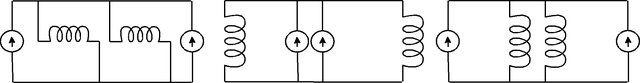
Last but not least, CA allows us to layout our diagrams and circuits freely without changing their behavior. For example, the following three circuits are the same using CA, but most certainly not alike to Maxwell’s Equations.
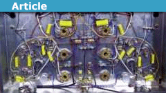
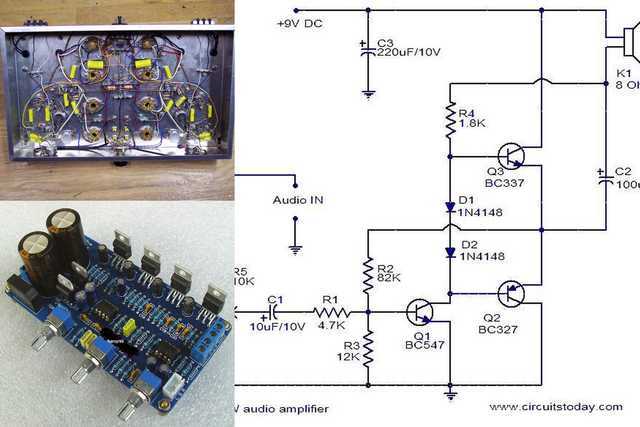
The same applies to the circuits in the pictures below. One is just a conceptual schematic, one built manually with a soldering iron and one built by robots with printed circuits. All three can in principle be identical for CA purposes, provided that we check that the assumptions are not violated. Cross-talk is a possible violation. Those physical circuits would be exceedingly hard to analyze using more rigorous Maxwell’s Equations and harder still using QED.
It is hard to imagine today’s electric and electronic industries even existing if we did not have the analytical power of CA at our disposal. It is only in special circumstances that the industry needs FT or QED analysis.
Pragmatic Modeling
Modeling (simulation) of physical systems is a two-step process. Step 1 is writing the equations that represent the physics. Step 2 is solving those equations. CA is the step 2 part of the process. It is a purely mathematical process, divorced from physics. The CA tools mentioned above are mathematical tools. Analysts are thus better off focusing on the analysis task and ignoring the physics.
It is tempting to think that idealized components (R, L, C, V, I, diode, transformer) are merely simplified versions of the real things. For example, an L is just an inductor where we neglect any resistance and parasitic capacitance it has in real life. But at the CA stage, we focus on the analysis. For example, in CA L is simply a ##\frac{dI}{dt}## term, nothing more.
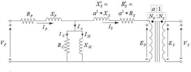
It is common practice to model real-life components using equivalent circuits of ideal components. For example, a real-life transformer violates the assumptions of CA, but the transformer equivalent circuit below (which includes an ideal transformer) complies with CA assumptions.
Why Are These Assumptions Unfamiliar to Many Experts?
Understandably, we teach many students topics in the order simplest first. [I’m sure there are exceptions to that.] If we teach CA first, then FT second, and QED last, where is the logical place to insert these assumptions? Before CA they make little sense. After FT they seem moot. But if we taught in the order fundamental first to pragmatic last, we would start with QED, then FT, and CA last. Injecting the assumptions after FT and before CA would be natural. So, it is my opinion that these assumptions get lost as a consequence of our teaching methods.
Dealing With Conduction Questions on PF
A recurring problem on PF is raised by students who may have learned about components and CA and wish to go a “little bit” deeper to understand electrical conduction. To make it worse, many are unwilling to go further with serious study and unwilling to deal with math beyond what they already know. Sometimes, the tip-off is when the student mentions electrons.
On the other hand, we have PF veterans who wish to help these students while avoiding pop-sci or lame analogies. How should we respond?
Let’s examine the problem. One can be an A-level student or even a professional using CA and FT without any mention of electrons. [Vacuum tubes, P-N junctions, Van de Graff, particle accelerators, and electric arcs are exceptions that do require explicit consideration of individual electrons.] It is at the quantum level where electrons become an essential part of the picture. Indeed, the correct description of conduction in my opinion is presented in the Wikipedia article Free Electron Model (which supersedes the earlier Drude Model). The article uses a mix of FT and crystallography, with quantum effects. It is difficult material requiring extensive prior study to understand.
So the answer seems to be a bitter pill. To the student’s question, “Can’t I go just a little bit deeper to understand conduction in a wire?” the correct answer is “No.” Most of us like to encourage inquisitiveness, so we hate saying no. But the laws of physics are not arranged to suit our convenience. Sometimes tough love is the best approach.
Dick Mills is a retired analytical power engineer. Power plant training simulators, power system analysis software, fault-tree analysis, nuclear fuel management, process optimization, power grid operations, and the integration of energy markets into operation software, were his fields. All those things were analytical. None of them were hands-on.
Dick has also been an exterminator, a fire fighter, an airplane and glider pilot, a carney, and an active toastmaster.
During the years 2005-2017. Dick lived and cruised full-time aboard the sailing vessel Tarwathie (see my avatar picture). That was very hands on. During that time, Dick became a student of Leonard Susskind and a physics buff. Dick’s blog (no longer active) is at dickandlibby.blogspot.com, there are more than 2700 articles on that blog relating the the cruising life.


Regarding the "Diamond Transistor": I think, the device we call "transconductance ampolifier , OTA" has two high-resistive inputs.
In contrast, the device called "Diamond Transistor" has one high-resistive as well as one low-resistive input.
That`s why it is a kind of current conveyor (CCII).
I thought a diamond amp was a transconductance amplifier.That's another name for it.
The advantage is you do not have to bias it on – current travels both ways.
Don't know why for sure, but if you use it instead of an a normal op amp for current to voltage conversion it tends to sound better according to those that have tried it – possibly because its better slew rate –
'Another dynamic advantage of CFAs is their relative immunity from slew-rate limitations because Cc is driven directly by the input buffer, which can supply virtually any current to rapidly charge/discharge Cc.'
Thanks
Bill
I thought a diamond amp was a transconductance amplifier.
To boil it down to one line, it would be an op-amp with a current output instead of a voltage output
I would assume the diamond transistor is not very popular because what you describe it being able to do can be done easily with op amps. Unless I misinterpret what you are describing.
For the gory detail of what is actually inside a diamond transistor see:
https://www.edn.com/electronics-blogs/analog-bytes/4438881/Quest-for-the-Ideal-Transistor-
In a circuit diagram it has the same symbol as a normal transistor but with two arrows in each direction – one from base to emitter and the other emitter to base indicating current can flow both ways – see fig 3 in the above link.
It’s also sold as a little IC eg the OPA 860:
http://www.ti.com/lit/ds/symlink/opa860.pdf
For some reason its not actually used much by the electronic guys I know, and when I was into electronics many many moons ago none of the circuits I mucked around with or saw in magazines used it, so may be out of production these days – but has some advantages – so I don’t know why.
Understanding whats going on at the naive level is a bit tricky as I explained – but it’s simple when looked at the right way – its just current must go somewhere – if the base is clamped to earth it cant go there so must go through the collector and its load. Of course when you look at the actual circuit of one of these things as in the above link its not that at all – that’s the tricky bit I have never really been able to figure out. Abstraction hides all sorts of difficulties.
Thanks
Bill
There is a device called a 'diamond' amp -That was interesting. Thanks. Are you able to make an equivalent circuit for a diamond amp?
CA as use by electronic engineers has some rather strange implications when applied to active devices like transistors.
There is a device called a ‘diamond’ amp – its a little IC that acts like an ideal transistor – current can flow both ways through the base -emitter. The current is then amplified and appears at its collector.
It’s sometimes used as the buffer for a current output DAC chip that likes to see a virtual earth.. What you do is you clamp the base to ground and the emitter to the output of the DAC chip and have a load such as a resistor on the collector. Because the current flows both ways and it has gain it will always try to keep emitter also at earth – if not current will flow through the collector and whatever is connected to the emitter until it is. This is since the base is clamped to the earth it can’t go there – no potential difference so it must flow through the collector and its load – yet still sees a virtual earth. I have shown the circuit to a number electronic engineers I know – one even incorporated it in a DAC he built – but it takes a while to see it, its just a simple application of current laws – current must go somewhere.
That of course is the ‘naive’ analysis – what’s really going on I have tried and failed to understand – it is rather tricky.
Just as an aside I always thought the best output for a DAC chip was just a simple transformer. I got one of my electric friends to try it – it failed miserable with the PCM1704. But he told me when he switched to an AKM chip it worked great. Interesting.
Thanks
Bill
The What and Why of Circuit Analysis AssumptionsGreat insight article! That was also my first circuit analysis textbook, and I remember that introductory chapter with its explicit list of assumptions to this day! Personally, I wish that every textbook would start off with such an explicit list of the simplifying assumptions used in the theory.
As far as when to teach these assumptions, I think that it doesn't make sense to teach QED first, you would lose a vast number of students many of which can make good use of CA throughout their life but will never use QED. So CA needs to come first in a program of study. But even if a student never learns the more advanced courses, they should still know these assumptions. That way the students can tell if a given physical scenario is one that they can model with these tools or not. They may not know how to treat assumption-violating scenarios, but they will at least know that their familiar tools may not be up to the task.
I am friendly with a number of electronic engineers in the audio field and believe me they know circuit analysis backwards. I have tried and failed miserably to explain QM to them – they just don’t get it. QED – well that’s way off the landscape for them. Yet of course transistors rely on holes that are really quasi particles. They understand well how transistors and diodes work using the hole idea – but quasi particles – that they have great difficulty with.
Thanks
Bill
From the thread on helical antennas: How about the fact that between its 1/4WL self resonant frequency and 1/2WL self resonant frequency, an inductor exhibits capacitive reactance? So much for inductance being proportional to the square of the turns. :eek:
Great Insight and great comments!
Another common CA that greatly simplifies things, but can cause disastrous results if mismanaged…
Forgetting that PCB traces and wire harnesses and wires can and will act as transmission lines, not ideal 0 impedance connections.
Great article. A classic CA example are batteries.
It can be simplified to an ideal voltage source. But as you need more and more accuracy you add capacitance, inductance, and non linear elements. Before you know it you have a fourth order non-linear filter. That is before add series and parallel cells.
It might be needed, depending on your application, but if you are making a pwm based low power led driver run off a voltage regulator, is all that really necessary. Making assumptions simplifies design and analysis so much, as long as one is aware of the conditions of the assumption.
Perhaps the focus should be on how EM fields from one part of a circuit can alter the operation of another part,Thanks for the kind words, but that was not my focus. Non ideal behavior would make an interesting Insights article, but others like @berkeman who designs circuits, or @jim hardy who troubleshoots misbehaving ones are better qualified than I to write it. My expertise in on the tools that analyze circuits that do follow CA assumptions.
You may have heard of Spice. That is the kind of tool I mean. In power system analysis PSS/E is the tool. I wrote the first version of that software in 1971.
Analysts have tricks to use CA even when circuit behavior is non ideal. Consider the following picture showing two three phase circuits sharing the same transmission towers. The mutual coupling between the two circuits violates the CA assumptions big time. But analysts simply adjust the values of series reactance for both lines to compensate, then put them into the analysis as if they weren't mutually coupled. In other words, they fudge the data to avoid the need to use Maxwell's equations to model the entire power grid (which would be impossibly difficult.) The practice is akin to the transformer equivalent circuit that I showed in the article. Non-ideal behavior is approximated by ideal components and standard CA methods are used to solve the circuit.
View attachment 214066
A good topic to discuss! There are certainly many cases in real circuits where non-ideal behavior can have a huge affect. Just to offer a few suggestions:
I think the main point you are making here is that there are non-ideal behaviors in real circuits which do not fit the assumptions of CA. You gave some of these assumptions, so maybe you could show some explicit cases where the assumptions are violated and what the correct solution would be.
I think the references to QED and FT somewhat detract from your main point. Perhaps the focus should be on how EM fields from one part of a circuit can alter the operation of another part, such as with the multiple inductors in the schematic shown.