The Poor Man’s Milli-Ohm Meter
Table of Contents
Introduction
In a previous article on measuring battery internal resistance, a simple technique for low-resistance measurement was outlined. In this article, the technique has been modified and expanded somewhat although the basic method remains the same. It is about as simple as it gets – one passes current through a reference resistor in series with an unknown resistance and then one measures the respective voltages. It should be noted that although we have employed two multimeters for the measurements described below, strictly speaking only one is required (a “poor man” or woman may typically have only one multi-meter at his/her disposal!).
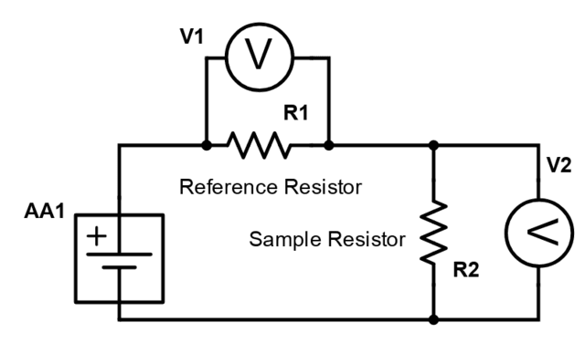
$$ V1 = IR1 $$ and $$V2 = IR2.$$ From which: $$R2=\frac{V2}{V1}\times R1.$$
One wonders why commercial milli-ohm meters are generally rather expensive items when – in principle – no more than the above simple ratio equation is needed. Since standard multimeters easily measure milli-volts and milli-amps why not use them for milli-ohms as well? It turns out to be pretty easy!
Perhaps part of the problem arises from what one might term “legacy” issues. Accurate reference resistances were not easily available and one could not rely much on the ratio of measured voltages. However, both issues are easily overcome with modern digital technology. Voltage measurement on even a modest 2000 count DVM (such as the one this author has) is reliable and – in particular – the ratios of respective voltage measurements are reliable because of the underlying digital ‘count’ technology. A count of say 10 on one reading against a count of 1000 on another will yield a very exact voltage ratio of 1/100 or 0.01. And one may safely conclude that the resistance value of a sample measuring 10 counts will be exactly 1/100th of the reference resistance measuring 1000 counts. Binary “counts” are of course translated to actual voltage measurements for the DVM display but that should not make any difference to the reliability of the count ratio.
In respect of the reference resistor nothing much more than a low-value resistor of the order of 10 ohms is needed. This resistor might be either 1% or 5% tolerance against its nominal value but this is of no particular concern if one can accurately measure its value to 2 decimal places either by finding a friend with an expensive meter or by ‘bootstrapping’ the method described in this article. For example, I made use of my DVM’s ohm setting to measure a reference resistor at 465 ohms and then employed the described method to measure a (nominally) 10-ohm resistor at 11.23 +- 0.05 ohms. The reference resistance value of about 10 ohms is chosen so that a circuit current of between 100 and 150 milli-amps will flow if the circuit is driven by an AA cell.
Battery Technology
A key element of the system described above will be the voltage source supplying current to the series circuit. One could of course go the route of designing a constant voltage source but doing this introduces a level of complexity that is probably not even necessary. Perhaps the correct “engineering choice” in such a situation is to stick with the simplest possible voltage source: a single AA cell.
The “engineer” will however need to exercise some careful thought concerning which AA cell to use. Currents in the order of 100 milli-amps or so will cause rapid discharge and unstable voltages in many AA cells. For this reason one needs to aim at rechargeable AA cells and – in particular – AA cells with a high milli-amp hour rating so that energy use during measurement is almost negligible against the battery’s milli-amp hour capacity. Here the choice was a 2850 milli-amp hour AA cell with a very flat voltage profile over a discharge period of 10 hours at 0.1 C (285 milli-amps). 10 hours should allow for plenty of measurements even with a current draw of 285 milli-amps.
Another desirable characteristic of this particular AA cell is that it has very low internal resistance specified at less than 30 milli-ohms. A test was carried out in which it was found that the battery voltage fell 15 milli-volts from an open circuit value of 1279 to 1264 measured across a 5.7-ohm resistive load. This corresponds to a resistance of 68 milli-ohms made up of battery internal resistance and leads resistance. Since the latter was known to be 30 milli-ohms, the battery’s internal resistance is about 38 milli-ohms – a little more than specified but still very low. Probably the batteries I bought had been on the shelf too long since their initial emfs (measured before recharging) were a bit low.
Calibration
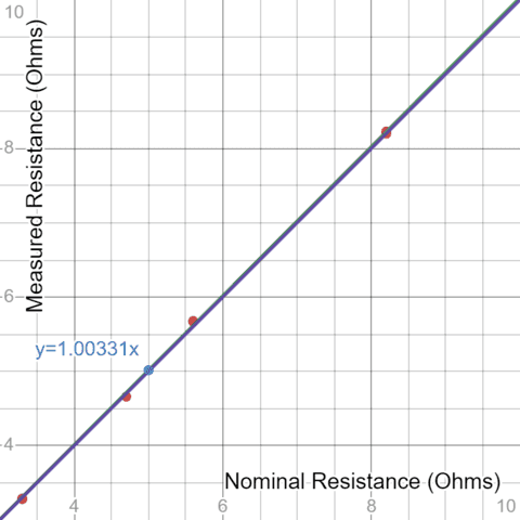
In order to check if this simple idea actually works in practice a number of low ohm resistors were measured according to the above method. At 5% tolerance, these were not particularly high precision resistors but one would imagine that statistically, the “actual” values would have an even chance of being either slightly above or slightly below their nominal values. So if one randomly selects a few of these and plots measured vs nominal values, the regression-determined gradient should be very close to unity. As can be seen from the following table and graph, the measurements passed their first test. It may also be noted that the actual measurements are well within the 5% tolerances of the various resistors selected. It will be interesting to conduct similar measurements on 1% resistors and see if the same applies.
Although 2 identical voltmeters were used to take the following readings, it was found that there was a slight discrepancy in voltages if the two were used to measure the same source voltage. Hence a small “voltage correction factor” of about 0.4% was applied to the voltage ratios when calculating resistance values.
| Standard Resistances | ||||
| Resistance | ||||
| Nominal Value (ohms) | Vitem | Vref | Ohms | Error % |
| 3.3 | 286 | 980 | 3.29 | -0.35 |
| 3.3 | 285 | 980 | 3.28 | -0.70 |
| 4.7 | 370 | 894 | 4.66 | -0.78 |
| 5.6 | 424 | 842 | 5.67 | 1.31 |
| 5.6 | 424 | 841 | 5.68 | 1.42 |
| 8.2 | 533 | 732 | 8.20 | 0.06 |
| 8.2 | 534 | 731 | 8.23 | 0.38 |
Plot of measured vs nominal resistance values (ohms):
https://www.desmos.com/calculator/h8xwo9fewd
Measuring Resistances less than 1 Ohm
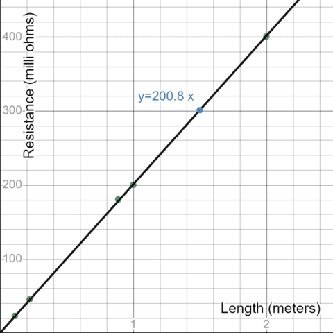
Encouraged by the above calibration results, the next step was to find some items exhibiting low resistance values of less than an ohm. The obvious candidate(s) here were lengths of 0.9mm diameter galvanized steel wire. Unfortunately, it was not easy to obtain a specific resistivity for this wire and the best that could be found on the internet was “less than 216 ohms/km”. That corresponds to “less than 216 milli-ohms” per meter. Aside from the accuracy of actual resistance values measured, one also expects an exact proportion between resistance and length.
When cutting various lengths of wire, we would have to admit that accurate measurement was somewhat hampered by inadequate tensioning of the wire. That is to say, the wire lengths were not properly straightened out before being cut to specific lengths. This error notwithstanding, there was good correspondence between measured resistance and lengths of wire cut and there is scope for further improving the accuracy of measurement (by tensioning the wire so that it is properly straight and then reading voltages across measured lengths).
A further point to be noted about the measurements below derives from a relatively “unheralded” feature of the meters used – namely that below 200mv, the 2000 count resolution permits readings down to 0.1 milli-volts. This extra degree of voltage measurement precision improves the accuracy of resistance measurement by an order of magnitude.
| Steel Wire Resistances | |||
| Resistance | |||
| Length of Steel Wire (meters) | Vitem | Vref | Milli-ohms |
| 0.111 | 2.6 | 1270 | 23.1 |
| 0.222 | 5.1 | 1265 | 45.4 |
| 0.888 | 20.1 | 1255 | 180.5 |
| 1 | 22.1 | 1244 | 200.2 |
| 2 | 43.7 | 1229 | 400.7 |
Plot of Resistance vs Length of Steel Wire
https://www.desmos.com/calculator/wzmrhuom7k
Measuring Resistance down to 1 Milli-Ohm: The Steel Ruler Test
A more stringent test of the measuring system’s capability is the measurement of resistance across various lengths of a steel ruler. From an online search, it was found that steel rulers are made from a particular type of steel: namely martensitic steel. If the reader clicks on the link for “martensitic steel”, a page of properties displays, and the electrical resistivity is given as ##6\times 10^{-5}\;\Omega cm## or ##6\times 10^{-7}\;\Omega m##. The particular ruler being measured is of length 60 cm, width 29 mm, and thickness 1 mm. Hence its theoretical resistance across the full length of 60 cm can be calculated as follows: $$R_{60}=\frac {6\times 10^{-7} \times 0.60}{29 \times 10^{-6}}=0.0124\;\Omega=12.4\;m\Omega.$$
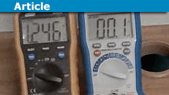
Here is a picture of this resistance being measured. We would like to display both contact points on the ruler but the picture becomes a bit too ‘elongated’ if we do. We hope readers will accept on trust that the other end(s) of the leads are on the out-of-view end of the ruler.
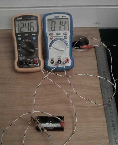
Measurement of Resistance across 60cm Steel Ruler
From this measurement we obtain: $$R_{60}=\frac{1.4}{1246} \times 11.23 \approx 0.0126 \;\Omega = 12.6\; m\Omega$$ which is in good agreement with the theoretical value determined above.
Since the measurement is 1.4 milli-volts, we can theoretically measure the length of the ruler right down to ##\frac{60}{14}\approx 4.3 cm## which should measure 0.1 mV reflecting a resistance of ##\frac{12.5}{14} \approx 0.9 \; m\Omega.## Let’s do just that:
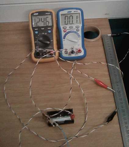
Measurement of Resistance from 20 to 24.3cm – Steel Ruler
In general, we expect an exact correlation between the volt measurements (and hence resistance measurements) and the length of the ruler measured. If we measure 1.4 milli-volts across 60 cm of the ruler, then we should of course measure 0.7 milli-volts across 30cm, and in general we do. This quite exact linear relationship gives us further confidence in the measurements being made.
See also this video in which the same measurement was repeated using a lower reference resistance (5.68 ohms). With apologies to Johan Strauss (the younger), we trust readers will forgive the “YouTube theatricals”!
Error Margins
If we are measuring a resistance of around 10 milli-ohms against a reference resistance of (say) 10 ohms, the ratio is 1000:1. This means that if the voltage across the sample changes by 0.1 milli-volts, the voltage across the reference resistor would change by 100 milli-volts. Thus as a rough guide to error margins, assume the reading of 1246 mill-volts above is “mid-range”. This means it could be as high as 1246 + 50 = 1296 mill-volts or as low as 1246 – 50 =1196 and accordingly we would need to write: $$\frac{1.4}{1296} \times 11.23 \leq R_{60}\leq\frac{1.4}{1196} \times 11.23 $$ $$\implies 12.1 \leq R_{60} \leq 13.1 \; m\Omega$$
Data Sets
Following a review of this article, it was suggested that “experiments using multiple readings of the same resistor with different meters, and in different ambient conditions” are carried out. Accordingly, 2 low value resistors having nominal values of 5.6 ohms and 8.2 ohms respectively were measured multiple times using a standard resistor with an accurately measured value of 1006 ohms. Two different pairs of meters were used along with 6 different pairs of AA cells connected first in series and then in parallel. For good measure one of two (in each pair) was chosen and the experiment was repeated with a single cell. The overall outcomes of all these measurements were as follows.
Resistor 1 (nominally 5.6 ohms): ##5.678 \pm 0,014 \Omega## n=41
Resistor 2 (nominally 8.2 ohms): ##8.195 \pm 0.019 \Omega## n=62
Measurement of low-value resistances to 2 decimal places has been achieved within the tolerances indicated by the standard deviation values above. The data sets from which the above were obtained can be viewed in this Google spreadsheet. Detailed statistical summaries and density plots for the measurements on the 5.6-ohm nominal and 8.2-ohm nominal resistance values can be viewed by clicking on the respective links.
Comparison vs commercial Milli-Ohmmeter Readings
Some low-resistance items were measured using the technique described herein and also using a commercial Milli-Ohmmeter: a Major Tech MT 985. Most readings correspond to within 5%. In the case of the steel ruler, one might even ask questions about the commercial measurement, since our reading is closer to the theoretical value! With measurements at the milli-ohm level, one also has to be extremely careful to ensure connection points for both “meters” are the same. Even the length of a crocodile clip is enough to register one or two milli-ohms leading to a few percent difference in comparative readings.
Table of comparative measurements.
Conclusion and Suggested Improvements
The measurement results obtained above should provide a “proof of concept” for a very simple milli-ohm meter design. The calibration data using standard low-value resistors shows clearly that the voltage ratios measured do indeed reflect the corresponding resistance ratios. Measurements of various lengths of steel wire display a very accurate correspondence between length and resistance so – despite not having an exact number for the resistivity of galvanized steel wire – we are confident of the various resistance values (less than 1 ohm) obtained. In respect of the steel ruler, the measured value of resistance across 60cm was in good agreement with that calculated using the given value of resistivity for “martensitic steel”. The steel ruler measurements also confirmed the well-known proportionality between conductor resistance and length given a uniform cross-sectional area.
Greater examination of tolerances and error margins would need to be undertaken but there are clear paths forward to enable better measurement resolution and lower error margins. The most obvious improvement is simply to employ meters with higher ‘count’ analog to digital converters. Secondly one could easily use lower values for the reference resistor – the single 2850 milli-amp hour AA cell delivers excellent results (for example) when a (nominally) 5.6-ohm reference resistor is used instead of the (nominally) 10-ohm resistor.
A careful design for a robust battery holder could also be considered and should accommodate 3 or even 4 AA cells in parallel so that energy drawn during measurement is a tiny fraction of battery capacity. C-cells or even D-cells could also be used to provide greater battery capacity. Connectors and terminals should all be solid copper so that there are minimal voltage drops across “fitment resistance”. It might seem somewhat incongruous to design heavy industrial terminals for AA batteries but, in an industrial setting, one might well need to employ (for example) battery jumper cables to connect to thick electrical cables and/or transformer or motor windings to measure low-value resistances.
Acknowledgments
I would like to express my sincere thanks to PF user @scottdave who reviewed the article and suggested the collection of the above data sets as well as the table of comparative measurements. PF user @TomG also commented on various aspects of the article as well as suggested some useful wording changes.
Major Tech (Johannesburg) kindly assisted with comparative milli-ohm measurements using their MT985 milli-ohmmeter.
I would not have “Insights Author” against my name were it not for the ongoing encouragement and support of @Greg Bernhardt. Always appreciated.
References
| [1] | Ginifab. Stainless Steel Ruler.https://www.ginifab.com/stationery/stainless_steel_ruler_wholesale_mm_metal.html. (Accessed on 04/27/2023). [ bib ] |
| [2] | Mat Web. 440c Martensitic Stainless Steel (uns s44004).https://www.matweb.com/search/datasheet.aspx?matguid=850c5024f8d844af8ef95afab1a08792&ckck=1. (Accessed on 04/27/2023). [ bib ] |
BSc (Elec Eng) University of Cape Town, HDE University of South Africa
Maths and Science Tutor, Florida Park, Johannesburg
Research areas (personal interest): Hydrogen / Hydrogen-like spectra. Historical Maths.
Wikipdedia contributions: Ptolemy’s Theorem, Diophantus II.VIII, Continuous Repayment Mortgage


Leave a Reply
Want to join the discussion?Feel free to contribute!