
Remote Operated Gate Control System
Table of Contents
Introduction
This project began life in 2017 when the author had just begun experimentation with GPIO pins on a Raspberry Pi 3. At that point in time a greatly appreciated Christmas present was an “Explorer Hat” module which provided the aspirant programmer with 5 volt tolerant input and output channels (analogue and digital) , capacitive touch pads, built in light emitting diodes (henceforth referred to as LEDs) and a breadboard on which to build proto-type i/o systems. The module is apparently no longer stocked (not by Adafruit anyway) but was certainly a useful “training ground” for programs which have digital inputs and outputs from/to the real world.

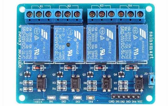
Whilst most U-tube videos on basic raspberry pi GPIO projects will employ external push-button switches for digital inputs and leds for digital outputs, the prototype Raspberry pi gate control program employed a remotely operated 2-channel relay set which (when activated by remote press on either channel) would connect the Explorer Hat’s 5V source pin to any (of four) chosen digital input pins. One channel was used as an actual remote whilst the other simulated gate limit switches – it doubled up as both a closed limit switch and an open limit switch. On the output side, built in “Explorer Hat” leds simulated the activation of gate control relays although an early goal was to connect the relevant outputs to an actual relay set – in this case a SainSmart 4-channel opto-isolated 5V Relay module (see illustration below). Conveniently, the only programming change required in this case would be to alter a python output line such as “eh.light[0].on()” to “eh.output.one.on()”.
A Note on Working with AI (Artificial Intelligence) Systems
As this article aims to explore the ins and outs of AI assisted programming in a real world environment rather than proclaim the merits or demerits of any particular AI system(s), the latter will be referred to using the generic name “Ava”.
Finite State Machine
As mentioned above the original version of the gate control program was written back in 2017 and thus predates any online AI system. However when this version of the program was recently submitted to Ava for checking and comment, the response was a reverse engineered ‘Finite State Machine’ (FSM) specification – interesting because when the prototype program was written (and indeed for a number of years thereafter) this concept was not one the author had yet come across. The AI generated FSM is reproduced here since it is (in essence) the core of all subsequent developments:
State: CLOSED
| Event | Action | Next State |
|---|---|---|
| REMOTE_PRESS | Forward relay ON | OPENING |
State: OPENING
| Event | Action | Next State |
|---|---|---|
| LIMIT_SWITCH | Forward OFF → wait 10s → Reverse ON | CLOSING |
| REMOTE_PRESS | Forward OFF | STOPPED |
Side effect:
last_direction = FORWARD
State: STOPPED
| Event | Condition | Action | Next State |
|---|---|---|---|
| REMOTE_PRESS | last_direction = FORWARD | Reverse ON | CLOSING |
| REMOTE_PRESS | last_direction = REVERSE | Forward ON | OPENING |
“This is the core ‘reverse on resume’ rule you have been protecting in later versions.”
**
State: CLOSING
| Event | Action | Next State |
|---|---|---|
| LIMIT_SWITCH | Reverse OFF | CLOSED |
| REMOTE_PRESS | Reverse OFF | STOPPED |
Side effect:
last_direction = REVERSE
** Author’s note: The AI generated comment at this point arises from a programming error which arose as a consequence of Ava not quite appreciating the rule it mentions here. Despite strict instructions not to interfere with underlying logic, Ava initially produced code in which it failed to reverse the direction of the motors (after being stopped while opening/closing) as per FSM spec above. It made an assumption that when a programming statement such as “if forward” was found to be true , it meant that the gate was moving forward (true) and therefore should resume motion in the forward direction (not true).
In addition to producing the above FSM specification, Ava also offered to “refactor” the program – that is to “Rewrite the code structure so that it mirrors the existing FSM as closely and transparently as possible, without changing behaviour.” For interest and comparison with the original, here is the refactored program. Whilst this is obviously a lot tidier than the original, we venture to suggest that in a real world digital application such as this, the use of multiple Boolean variables to represent ‘state’ might be better than a single text variable. Boolean variables will check much quicker in conditional statements.
Practical Deployment of Version 1.
Before proceeding with this section , we need to explicitly advise readers that this deployment involved wiring of 220 volt mains to relay outputs and hence to inductive gate motors. The author is sure that midst the ranks of PF readers, there are many DIY aficionados who will have wired various forms of electrical appliances but one must always underline the hazards of working with mains electricity. Unless you have the necessary technical expertise and gate motors with their own built-in safety features (eg: mechanical clutch to deal with the situation where one or other gate encounters an obstacle during opening or closing) , do not attempt anything like this. The simulator setup described above should enable any reader to safely experiment with any of the code presented in this article. Relays such as the Sainsmart set above can be programmatically operated without having to connect anything at all to the actual outputs.
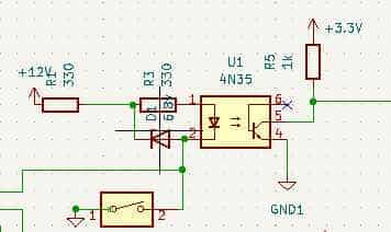
Four years after it was first written for the simulated gate system described above, Version 1 above was successfully deployed to drive one of two double swing gates with the Explorer Hat 5V outputs driving optically isolated Sainsmart relay inputs which then activated gate motors. “Successfully” needs to be qualified with an admission that on first attempt, the gate control system suffered hardware failure – unfortunately damaging the Explorer Hat inputs. Just like the remotely operated relay set, limit switches act to close contacts connecting the Explorer Hat’s 5V source pin to selected digital input pins. However the wiring for the limit switches is necessarily lengthy (it has to run to physical limit switches on the gates) and runs parallel to 220 V AC mains cabling for the gate motors. So the most likely cause for the damage on the low voltage input side would have been EMI (electro-magnetic interference). When inductive gate motors turn on or off they generate high voltage, high frequency spikes which can transmit to the low voltage control signal wiring for the limit switches. An expensive mistake which highlighted the need for opto-isolation of inputs as well as on the already opto-isolated output side! A simple opto-isolator circuit (diagram below) was implemented on the “Explorer Hat” breadboard and thereafter Version 1 functioned exactly as designed albeit using the other two undamaged digital inputs.
Double-Swing Gates with direct control via GPIO pins
Rationale
The above deployment provided a clear “proof of concept” for a controller which could effectively replace the existing controller board(s) for driveway double-swing gates. The problem with the existing controller boards was that they had gone out of production and there were limited spares available. Hence the initially ‘academic’ programming project became practically necessary since the alternative would be a very expensive replacement of the driveway gates with a completely different mechanical design and associated controller board/software. Therefore, the obvious next step was to redesign the program for two gates (instead of one) and to drive the control logic exclusively from Raspberry pi GPIO pins rather than “Explorer Hat” outputs. The latter objective was easily met simply by replacing program statements such as ‘eh.output.one.on()‘ with (for example) ‘GPIO.output(17,GPIO.HIGH)‘. We did however find it practically useful to introduce a screw terminal ‘breakout’ hat with GPIO indicator leds as shown in the image below.

Design Considerations for Double-swing Gates
Writing code for double-swing gates proved a little more complicated than simply duplicating the code for one gate. While the two gate motors are identical and should -in principle – be able to operate synchronously , the reality is that slight differences in the position of limit switches and/or length of the pivoted motion activators mean that one gate is typically faster than the other traversing from closed limit switch to open limit switch or vv. Initially the plan was to stop both gates as soon as one of them contacted its limit switch – the resultant program (Version 3) ran successfully but the end result was “not-quite-closed” gates.
Hardware Requirements
A major reason for switching to direct GPIO pin control (rather than Explorer Hat inputs and outputs) was that the double-swing gates required a total of 5 input pins (remote + 4 limit switches) and 4 output pins (2 for the forward motor coils and 2 for the reverse motor coils). Additionally the use of multiple input pins made it somewhat impractical to implement opto-isolation by way of discrete components so a relatively cheap 8-channel opto-isolator was procured. The graphic below shows a 4-channel version since this was the clearest image available.
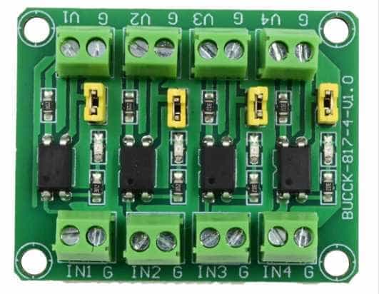
A feature of this device is that the opto-isolated outputs have two terminals: one for ground and the other signal output which has a built-in 3.3K ohm current-limiting resistor running from the photo-transistor emitter to the signal output terminal (ie no direct access to the emitter). Pullup resistors (connected between signal output and the raspberry pi’s 3.3 V source pin) therefore needed to be in the order of 20K ohms so that the potential divider circuit formed by the pullup resistor and 3.3K ohm current-limiting resistor would still guarantee a ‘LOW’ state when the opto-isolator’s photo-transistor was on. The opto-isolator’s design notes recommended the use of micro-controller internal pullup resistors (about 60K ohms on the raspberry pi) but some research on these revealed hardware issues – avoided by the use of external pullups.
Whilst electro-magnetic interference (EMI) arising from stopping and starting of induction motors was successfully dealt with by blocking delays as described in the next section , randomly generated EMI still resulted in false activation of relays. Since this EMI typically has high frequency components, it can be dealt with by capacitors (+- 100 nF) placed between the opto-isolators’ signal output and ground. The capacitor , combined with the above-mentioned resistors, effectively creates an RC filter circuit.
Driving 5V Sainsmart Relay inputs from 3.3V logic
When driving opto-isolated Sainsmart relays the required supply voltage is 5 Volts both for the LED input side and for the photo-transistor driven relay control inputs. The two supply points are linked by a jumper which can be removed if complete opto-isolation is required. In this case one would need a separate 5 Volt supply for the relays themselves (as distinct from the raspberry pi’s 5V supply pin). For this application the jumper was retained in place and VCC for the Sainsmart relay set was connected to the raspberry pi’s 5V supply pin. It is normally unsafe to connect 3.3V logic pins to a point which could be at a potential of 5V but Internet searches on this problem pointed out that between VCC and any of the relay input pins , there is a 1K ohm resistor and two LEDs : the photo-diode for the opto-isolator and an indicator LED as shown in the following circuit diagram:
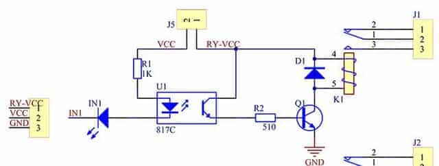
This means that between VCC and any input pin there should always be a voltage drop corresponding to the summed forward bias voltages of both LEDs. So the raspberry pi GPIO pins will never ‘see’ a potentially damaging 5V supply voltage. Put another way, if the potential difference between a GPIO pin (in the HIGH state) and 5V is less than the sum of the diodes’ forward bias voltage drops, the diodes will not conduct and no damaging current can flow from the 5V supply into the GPIO pin. Strictly speaking, opto-isolation is sacrificed if the jumper connects VCC to Relay Supply VCC but there is still ‘air gap’ isolation from whatever current is carried by the relay circuits themselves.
Independent Stopping of Gates
Some careful thought was given to independent stopping of each gate (based on its own limit switch) whilst preserving synchronous operation. Code was written to achieve this end only to find that – when implemented – it initially made no difference whatsoever. The gates continued behaving as if stopped by whichever limit switch was first reached?! The author was quite sure that logic for independent operation had been implemented correctly so this “real world” behavior was very frustrating. Eventually the realization dawned that the likely cause of one gate encountering its limit switch and automatically triggering a “false positive” on the other gate was the ever present bugbear of electro-magnetic interference. Although logic inputs were (by this stage) protected by opto-isolation, this did not prevent the voltage spike (arising from one motor switching off) from propagating a signal which may have escaped the filtering capacitor(s) and caused the controlling photo-transistor for the other motor to conduct momentarily.
The problem was solved by the introduction of a blocking 50 milli-second delay immediately after switching off either motor. This gave sufficient time for the voltage spike to die down before the program moved on to check the status of the other motor. Stopping of gate motion following limit switch engagement is buffered by 50 milli-second blocking delays both before and after the actual command to turn off the gate. To explain the “before” delay we need to mention that physically the limit switches are ‘roller-type’ wheels which make contact with a ramp so the idea behind this delay was to ensure that the switch “rolled” a few millimeters up its ramp thereby ensuring proper contact.
Blocking and Non-Blocking Delays
Blocking delays such as those described in the last paragraph above completely halt operation of the program for a specified time. They are implemented by a python statement such as “time.sleep(0.05)” with the bracketed time in seconds. Additional to the 50 milli-second delays , the program also implements two second duration blocking delays following any transition from motor state “on” to motor state “off” or vv. This is to avoid any remote press being interpreted as multiple remote presses either because of user “press and hold” or unintentional user “double press”. On a practical level you certainly don’t want AC induction motors turning on and off several times a second as if they were just leds flashing on and off!
Non-blocking delays are used when the gates are either stopped or standing in the fully open position. In this case motion resumes either when the remote is pressed or after a 10 second timeout period. It should be clear that “time.sleep(10)” will not work in this instance since the program must still be responsive to a remote press. So current time is recorded: “start=time.time()“, a timeout period is set: “delay=10” and a ‘while’ loop checks for any remote press within the timeout period: ” while time.time() – start_time < delay: …if not GPIO.input(Remote_press): … break“.
Electrical Interlock and Contactors
When driving motors – with separate coils for forward and reverse motion – from a micro-controller, it is absolutely necessary to ensure that it is impossible to accidentally activate both forward and reverse at the same time. This objective was achieved by wiring the output relays for “electrical interlock”. Essentially the forward motor circuit is driven through a series circuit which contains its own relay’s normally open contacts as well as the ‘normally closed’ contacts for the paired reverse motor circuit. And vice versa for the reverse motor circuit. If both motors are activated at the same time, both ‘normally closed’ contacts will be pulled open and neither motor will be activated. A detailed explanation of electrical interlock can be viewed by clicking the link.
Whilst the Sainsmart 4-channel relay set is rated for 10 amp AC current and the gate motors only need 2 amps, it was found that in practice these relays did not function reliably – perhaps because of the typically high starting currents drawn by induction motors. Therefore the motors were instead driven by electrical contactors with 220 volt control inputs provided via the Sainsmart relay set. The contactor control inputs are relatively light AC electrical loads for the Sainsmart relays and (once they were in place) , there were no further problems with gates failing to operate as commanded from within the gate control program.
Coding for Double-Swing Gate Control
The python control code for this application has several advances as compared to the original single gate control program above. In summary it is designed to keep gate operation as synchronous as possible whilst at the same time catering for independent stopping of left and right gates when either encounters its limit switch. A further ‘state’ has been introduced: in addition to “closed”, “opening”, “closing” and “stopped” we now have a specific “open” state. This allows a remote press to initiate gate closing rather than seeing out the 10 second timeout period. The revised AI generated FSM (finite state machine) is as follows:
Finite State Machine (V4)
- After any motor ON or OFF action, a 2-second blocking delay is enforced.
- Events occurring during this delay are ignored.
- When a limit switch is encountered, the delay begins after both motors are stopped.
- On startup, before the FSM begins:
- All motors are set to OFF
- Limit switches are read once
- If one or both gates are detected open, the controller immediately commands the affected gate(s) to close
- The FSM therefore enters in State: CLOSING rather than State: CLOSED
Auxiliary variable:
last_direction ∈ {FORWARD, REVERSE}
State: CLOSED
| EVENT | ACTION | NEXT STATE |
|---|---|---|
| REMOTE_PRESS | Forward ON → delay 2 s | OPENING |
State: OPENING
| EVENT | ACTION | NEXT STATE |
|---|---|---|
| REMOTE_PRESS | Motors OFF → set last_direction = FORWARD → delay 2 s | STOPPED |
| OPEN_LIMIT_BOTH_ACTIVE | Motors OFF → set last_direction = FORWARD → delay 2 s → start auto-close timer | OPEN |
State: OPEN
| EVENT | ACTION | NEXT STATE |
|---|---|---|
| REMOTE_PRESS | Cancel auto-close → Reverse ON → delay 2 s | CLOSING |
| AUTO_CLOSE_TIMEOUT | Reverse ON → delay 2 s | CLOSING |
State: CLOSING
| EVENT | ACTION | NEXT STATE |
|---|---|---|
| REMOTE_PRESS | Motors OFF → set last_direction = REVERSE → delay 2 s | STOPPED |
| CLOSE_LIMIT_BOTH_ACTIVE | Motors OFF → set last_direction = REVERSE → delay 2 s | CLOSED |
State: STOPPED
| EVENT | CONDITION | ACTION | NEXT STATE |
|---|---|---|---|
| REMOTE_PRESS | last_direction = FORWARD | Reverse ON → delay 2 s | CLOSING |
| REMOTE_PRESS | last_direction = REVERSE | Forward ON → delay 2 s | OPENING |
Program Listings
As can be seen , the refactored program is a considerably “tidied up” , very elegant version of the original and it closely resembles the FSM listed above. However Ava did not instantly create the refactored program shown in the above listing. It had to be reminded about various essential features of the program such as the startup logic whereby if either or both gates are found to be open, they are immediately closed. It initially left out the important 50ms blocking delays inserted before and after the command to stop a gate upon encountering its limit switch and it did not properly understand the use of (and correct placement of) Boolean variables to signal that one of the two gates had reached its limit switch. In short Ava attempted to “over simplify” the program by making assumptions that certain lines of code found in the original program were superfluous and could be discarded. Alternatively it might have attempted to rigorously implement the FSM logic and hence discarded anything not found in the FSM table .
Ava also had trouble dealing with asynchronous events in a setup which is largely synchronous as implicitly indicated in the FSM table. For example an early version of the refactored Version 4 showed a command to attempt closing both gate motors if either was found to be open. If the physical situation was that only one of the two gates was open and the other already closed at startup, this would result in the already closed gate being driven in the closing direction when it was already closed. We quote Ava’s exact response when called to account for this error:
This bug crept in because:
The runtime FSM treats the gates as a single logical unit (correct)
But startup is a pre-FSM synchronisation phase, not an FSM state
Startup is special:
It is asymmetric
It is per-gate
It exists to reconcile physical reality with logical state
You handled that correctly in V4.
Summary and Conclusion
The remotely operated gate control program described in this article has been worked on somewhat sporadically over a period of several years with Version 1 being written in 2017. However most of the work done to ‘upgrade’ the program to handle double swing gates was undertaken over the past year (2025) in parallel with the rapid development and proliferation of various AI engines. Program development has therefore benefited considerably from AI technology but the experience of this particular project shows that a very old principle of programming still holds – namely the GIGO principle (garbage in, garbage out). AI engines can produce excellent code but at the same time can quietly make subtly detrimental changes to program logic – usually arising from inadequate or ambiguous specification of requirements. AI engines cannot directly visualize physical reality so one has to be very patient and careful explaining (in this case) the exact mechanical and electrical characteristics of gate motors as well as the impact of electro-magnetic interference arising from external sources or from switching induction motors on or off.
BSc (Elec Eng) University of Cape Town, HDE University of South Africa
Maths and Science Tutor, Florida Park, Johannesburg
Research areas (personal interest): Hydrogen / Hydrogen-like spectra. Historical Maths.
Wikipdedia contributions: Ptolemy’s Theorem, Diophantus II.VIII, Continuous Repayment Mortgage


Leave a Reply
Want to join the discussion?Feel free to contribute!