Reversible vs Irreversible Gas Compression and Expansion Work
Table of Contents
Introduction
In learning Thermodynamics, one of the difficult concepts that many students struggle with is the difference between reversible and irreversible work in the expansion/compression of a gas. They wonder,
1. Why is it that we need to use two different equations to calculate the work done by the system on the surroundings, one for a reversible process (##dW = PdV##, where P is the gas thermodynamic pressure calculated from the ideal gas law ##P =nRT/V##), and the other for an irreversible process (##dW = P_{ext}dV##, where ##P_{ext}## is the external force per unit area exerted by the surroundings (the piston face) on the gas?
2. Since, by Newton’s third law, the external force per unit area exerted by the surroundings on the gas ##P_{ext}## is equal to the gas thermodynamic pressure at the interface P, shouldn’t the equation ##dW = PdV## for reversible processes also correctly give the work for the irreversible process?
3. What is it fundamentally about irreversible processes that cause the amount of work done by the gas on the surroundings to differ from that for a reversible process?
In the present development, we will address all three of these questions, but our initial focus will be on question 3. Once we explore the answer to this question, the answers to questions 1 & 2 should become more apparent.
A gas experiencing expansion/compression work behaves in a manner very similar to a spring-damper mechanical system (with the spring and damper connected in parallel, Fig. 1). The spring response is analogous to P-V-T behavior of the gas, in the sense that decreases in length of the spring result in greater compressive force, while decreases in the volume of the gas result in greater pressure. The viscous behavior of the damper is analogous to the viscous response of the gas, in the sense that the force required to compress the damper is proportional to the time rate of length compression of the damper, while the viscous compressive stress in a gas is proportional to the time rate of volumetric compressive strain.
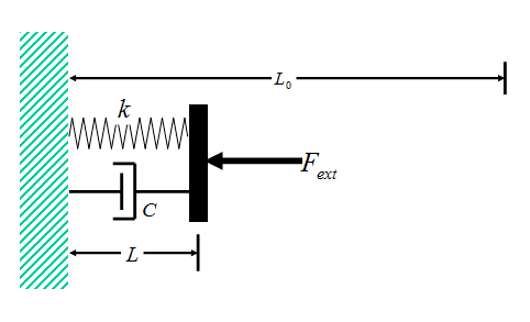
Figure 1 Spring-Damper Model
In the present development, we will begin by analyzing in detail the reversible and irreversible loading of a spring/damper combination and will show that the amount of work required to compress the system in the irreversible case exceeds that in the reversible case by the amount of work required to compress the viscous damper. We shall refer to this as the viscous work. The greater the compressive force ##F_{ext}## and the more rapid the deformation, the larger the amount of viscous work.
We will also note that the total external force required to compress the combined system ##F_{ext}## is not just that required to compress the spring ##F=kΔL##, but also includes a contribution from the viscous damper, and this contribution increases with increasing rate of compression. So we would not expect the applied external force to match that of the spring alone ##F=kΔL## unless the compression is carried out very slowly. This is analogous to the case of irreversible gas compression in which the external force per unit area ##P_{ext}## required to compress the gas is higher than the pressure calculated from the ideal gas law alone ##P =nRT/V##. The force also includes a contribution from the viscous stresses in the gas.
After we have completed our detailed quantitative assessment of the spring-damper system, we will turn our attention to the compression/expansion behavior of an ideal gas. While the spring-damper system is sufficiently simple to completely describe its time-dependent behavior for arbitrary transient loading with relative ease, this is not so in the case of an ideal gas. For an ideal gas, the detailed treatment is much more complicated and involves the solution to the complicated gas dynamics equations, including the Navier-Stokes equations, the local thermal energy balance equation (including viscous dissipation), the ideal gas law, and the local continuity/mass-conservation equation. Fortunately, in the special case of a constant external force per unit area ##P_{ext}## applied to the gas, these difficulties can be circumvented, and the total irreversible and reversible work can be determined relatively easily. We will compare these results for an ideal gas with the corresponding findings for a spring-damper system to illustrate quantitatively how closely they resemble one another.
Spring-Damper Model Analysis
Consider the spring-damper system shown in Fig. 1. The spring and damper are connected in parallel, and the combination is sandwiched between a wall on the left, and a plate on the right. A time-dependent external force ##F_{ext}## is applied to the plate, such that, at all times t < 0, the force ##F_{ext}=F_{i}##, while at all times t > 0, force ##F_{ext}=F_{f}##. The force ##F_{ext}## thus changes discontinuously at time t = 0 (Fig. 2).
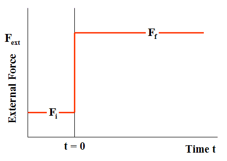
Figure 2 External Force Irreversible Loading (Case of compression)
The unextended length of the spring is ##L_0## and, to simulate the behavior of a gas (which can exhibit only compressive force), the spring is assumed to be loaded in compression throughout the entire time-dependent deformation of the system. Thus, the initial equilibrium length of the system ##L_i##, the final equilibrium length ##L_f##, and the length L at time t during the deformation are all less than ##L_0##.
The compressive force exerted by the spring (a) initially, (b) at time t, and (c) in the final equilibrium state of the system are related to the corresponding lengths of the spring by:
$$F_i=k(L_0-L_i)\tag{1-a}$$
$$F=k(L_0-L)\tag{1-b}$$
$$F_f=k(L_0-L_f)\tag{1-c}$$
Unlike the spring element, the compressive force exerted by the viscous damper ##f_V## is related not to the length of the damper L, but rather to the rate of change of the viscous damper length with respect to time:$$f_V=-C\frac{dL}{dt}\tag{2}$$ where C is the so-called “viscous damper constant.”
If we perform a force balance on the (massless) plate in Fig. 1, we obtain $$F+f_V=F_{ext}(t)\tag{3}$$ Note from this equation that the (reversible) spring compressive force is not the only load acting on the plate. There is also the (dissipative) viscous damper force applied to the plate. These two forces combine to determine the overall (constant) force ##F_{ext}## of the spring-damper system.
Substitution of Eqns. 1 and 2 into Eqn. 3 yields (for t > 0):$$k(L_0-L)-C\frac{dL}{dt}=k(L_0-L_f)\tag{4}$$The first term on the left-hand side represents the spring force, the second term represents the viscous damper force, and the right-hand side represents the constant loading force.
The solution to the this time-dependent differential equation for L, subject to the initial condition ##L=L_i## at t = 0, is given by:$$L=L_f+(L_i-L_f)e^{-(\frac{kt}{C})}\tag{5}$$As determined from Eqn. 5, Fig. 3 shows a plot of the dimensionless length ##L/L_0## as a function of the dimensionless time ##(kt/C)## for the specific case in which ##L_i/L_0=0.8## and ##L_f/L_0=0.2##.
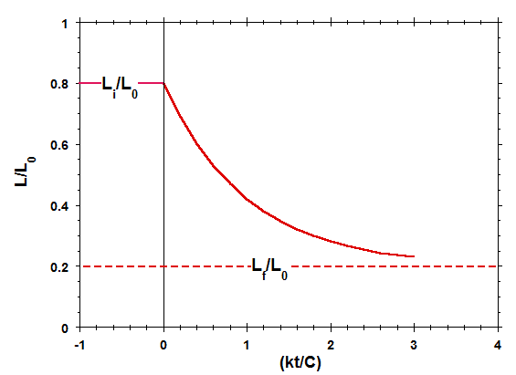
Figure 3 Length of Spring-Damper System vs Time
Comparison of Figs. 2 and 3 indicates that, for the situation currently being considered, while the applied external force ##F_{ext}##changes discontinuously at time t = 0, the length of the spring-damper element L varies continuously (and more gradually) from its initial length to its final length, on a time scale on the order of C/k. This more gradual variation is the direct result of the presence of the viscous damper element in the system. A similar effect occurs when a gas is forced to expand or compress in a cylinder, as a direct result of the viscous behavior of the gas (Yes, even in the low-pressure limit of ideal gas behavior, gases exhibit non-zero viscosity).
If we substitute Eqn. 5 into Eqns. 1 and 2 for the compressive forces within the system at times t >0, we obtain:$$F=k(L_0-L_f)-k(L_i-L_f)e^{-(\frac{kt}{C})}\tag{6-a}$$$$f_V=k(L_i-L_f)e^{-(\frac{kt}{C})}\tag{6-b}$$$$F_{ext}=k(L_0-L_f)\tag{6-c}$$Eqn. 6-a represents the force exerted by the spring, Eqn. 6-b represents the force exerted by the damper and Eqn. 6-c represents the total applied compressive force. Fig. 4 shows a plot of these three forces, normalized by ##k(L_0-L_f)##, and plotted as a function of the dimensionless time ##(kt/C)##, for the same compressional case that was considered in Fig. 3.
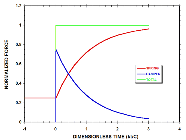
Figure 4 Normalized Spring-Damper System Forces (with ##L_f=0.2L_0## & ##L_i=0.8L_0##)
According to Fig. 4, the elastic spring continues to support only 25% of the applied load at the instant immediately after the external compressive force ##F_{ext}## is suddenly increased, while the damper, by deforming rapidly and viscously, supports the remaining 75% of the load. As time progresses, the rate of change of damper length with time decreases in magnitude, and the damper supports less of the load, while more of the load is borne by the spring. At the final equilibrium state of the system, the spring supports all the load, and the force of the damper has decayed to zero.
Let us now finally consider the reversible and irreversible work done by the spring-damper system. This can be obtained by multiplying each of Eqns. 6 by the rate of increase of length dL/dt derived from Eqn. 5, and then integrating concerning time from time t = 0 to t →∞. We thereby obtain:
$$W_R+w_V=W_{Irr}\tag{7}$$
with
$$W_{R}=\int_0^∞F\frac{dL}{dt}dt=\frac{k}{2}\left[(L_0-L_i)^2-(L_0-L_f)^2\right]\tag{8-a}$$
$$w_V=\int_0^∞f_v\frac{dL}{dt}dt=-\frac{k}{2}(L_f-L_i)^2\tag{8-b}$$
$$W_{Irr}=\int_0^∞F_{ext}\frac{dL}{dt}dt=k(L_0-L_f)(L_f-L_i)\tag{8-c}$$
where ##W{_R}## denotes the reversible work, ##w_{v}## denotes the viscous work, and ##W_{Irr}## denotes the irreversible work. Note that the damper constant C no longer appears in these equations, and thus these results for the work done between the initial and final equilibrium states of the system apply irrespective of the (non-zero) value of the damper constant. The reversible work ##W_R## represents that done by the spring alone and is also equal to the change in stored elastic energy of the spring. The irreversible work ##W_{Irr}## represents the combined work done by the spring and damper on their surroundings (the plate) and is determined by the applied external force integrated over its displacement. The viscous work ##w_V## represents the work done by the damper on the surroundings (the plate), and, by the squared term in Eqn. 8b, is always negative, irrespective of whether the system is being expanded or compressed. Thus, in all situations, the viscous damper robs usable mechanical energy from the surroundings and dissipates it as (less usable) thermal energy.
Fig. 5 shows a plot of the ratio of the irreversible work to the reversible work ##W_{Irr}/W_{R}## as a function of the expansion/compression length ratio ##L_f/L_i## for a typical case in which ##L_f=0.5L_0##.
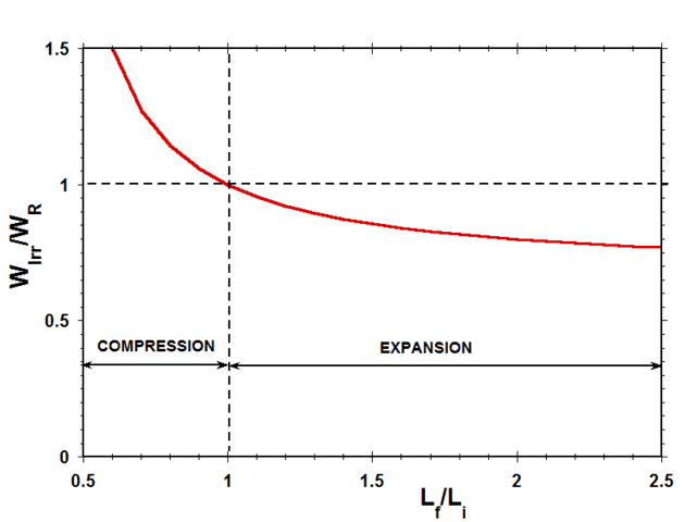
Figure 5 Ratio of Irreversible Work to Reversible Work vs Length Ratio (Case of ##L_f=0.5L_0##)
Considering work done by the system on the surroundings as positive, in expansion, both ##W_r## and ##W_{Irr}## are positive, while, in compression, both ##W_r## and ##W_{Irr}## are negative. Therefore, as indicated in Fig. 5, the ratio of ##W_{Irr}## to ##W_r## is positive for both expansion and compression. According to the quantitative results presented in Fig. 5, during compression, the irreversible work done by the external force on the system is always greater than the reversible work required to compress the spring, while, during expansion, the irreversible work done on the surroundings by the system is always less than the reversible work done by the spring. The difference between the reversible work and the irreversible work in all these cases is the result of viscous dissipation in the damper element.
In the next section, we will consider the comparison between reversible work and irreversible work for expansion and compression of an ideal gas and will present a graph analogous to Fig. 5 for this system. The quantitative comparison between these two plots will be very striking.
Ideal Gas Analysis
Consider the irreversible expansion or compression of an ideal gas contained in a cylinder featuring a massless frictionless piston (Fig. 6 – compared to Fig. 1). The system is immersed in a constant temperature bath (not shown) at temperature T so that the temperature of the gas in the initial and final equilibrium states of the system is T.
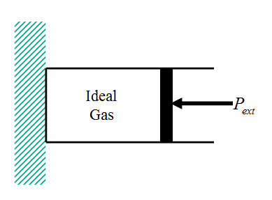
Figure 6 Ideal Gas Cylinder/Piston System
A time-dependent external force per unit area ##P_{ext}## is applied to the piston, such that, at all times t < 0, ##P_{ext}=P_{i}##, while at all times t > 0, ##P_{ext}=P_{f}##. The force per unit area ##P_{ext}## thus changes discontinuously at time t = 0 (Fig. 7, compared with Fig. 2).
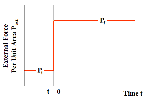
Figure 7 External Force Per Unit Area in Irreversible Loading (Case of compression)
The transient physical phenomena occurring within a gas that is irreversibly caused to expand or contract under the action of a sudden change in external force per unit area are substantially more complicated than those occurring in a simple spring-damper system and include
- non-uniform expansion and compression zones traveling back and forth along with the cylinder at speeds on the order of sonic velocities
- large temperature-, pressure-, and density gradients
- local regions of expansion cooling and compressional heating
- non-uniform viscous stresses
- turbulence resulting from the very rapid deformation, causing the gas to behave as if its viscosity were several orders of magnitude higher than the true laminar flow value
Even with all these complexities, the net effect of the change that occurs between the initial and final equilibrium states of the gas system is mechanistically exactly the same as in the case of the spring-damper system: The irreversible work ##W_{Irr}## is equal to the reversible work ##W_{R}## plus the work associated with viscous stresses ##w_{V}## (Eqn. 7).
In the case of the spring-damper system, we calculated the viscous work explicitly by solving for the transient viscous damper force and integrating over the transient displacement (Eqn. 8b). However, we could equally well have obtained the same result simply by subtracting the reversible work from the irreversible work (the equation for each of which is considerably easier to write down). In the case of the ideal gas, we now follow this latter approach. Thus, assuming the irreversible expansion is carried out at constant applied external force per unit area ##P_f=P_{ext}##, the reversible-, irreversible-, and viscous work for isothermal expansion/compression of an ideal gas are given by:
$$W_R=nRT\ln(V_f/V_i)\tag{9a}$$
$$W_{Irr}=P_f(V_f-V_i)=nRT\left(1-V_i/V_f\right)\tag{9b}$$
$$w_V=nRT\left[\left(1-V_i/V_f\right)-\ln(V_f/V_i)\right]\tag{9c}$$
Fig. 8 presents a graph of the viscous work ##w_V##, normalized by nRT, and plotted as a function of the ratio of the final- to the initial volume of the gas ##V_f/V_i## (Eqn. 9c).
Figure 8 Work Done By Viscous Stresses on Piston
The figure indicates that, as in the case of a viscous damper, the work done on the surroundings (i.e., the piston) by viscous stresses is always negative, irrespective of whether the gas is expanding or being compressed. Thus, as in the case of a viscous damper, the viscous response of the gas always robs usable mechanical energy from the surroundings and dissipates it in the form of (less usable) thermal energy.
Fig. 9 shows a plot of the ratio of the irreversible work to the reversible work ##W_{Irr}/W_{R}## for the case of an ideal gas as a function of the expansion/compression volume ratio ##W_f/W_i##.
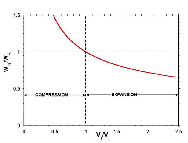
Figure 9 Ratio of Reversible Work to Irreversible Work vs Volume Ratio
Considering work done by the system on the surroundings as positive, in expansion, both ##W_r## and ##W_{Irr}## are positive, while, in compression, both ##W_r## and ##W_{Irr}## are negative. Therefore, as indicated in Fig. 9, the ratio of ##W_{Irr}## to ##W_r## is positive for both expansion and compression. This means that, during compression, the irreversible work done by the imposed external force per unit area on the gas is always greater than the reversible work that would have been required to compress the gas, while, during expansion, the irreversible work done against the imposed external force per unit area by the gas is always less than the reversible work that could have been done by the gas.
Finally, note the striking resemblance between Fig. 9 for the case of an ideal gas and Fig. 5 for the corresponding case of a spring-damper system. This comparison provides compelling evidence that the mechanistic cause of the difference between the reversible- and irreversible work in the irreversible expansion/compression of an ideal gas is the rate-dependent viscous work associated with deforming the gas.
Addressing Questions 1 and 2 of the Introduction
In a gas cylinder-piston system, the work done on the surroundings (i.e., on the inner piston face) is always equal to the time-dependent external force per unit area ##P_{ext}## applied at the face, integrated over the volume change. In the special case of a very slow reversible expansion/compression, ##P_{ext}## is also equal to the (uniform) gas thermodynamic pressure within the cylinder, as determined by the ideal gas law (or other real-gas equation of state). However, for a rapid irreversible expansion/compression, the thermodynamic pressure within the cylinder is not spatially uniform, and the external force per unit area ##P_{ext}## is not determined solely by the thermodynamic pressure. There is also an additive contribution from the viscous stresses present within the gas at the piston interface. Thus, even if we somehow knew the gas thermodynamic pressure at the piston face, this would still not be sufficient to determine ##P_{ext}##. In an irreversible expansion or compression, the only practical way to obtain a desired ##P_{ext}(t)## is to control it manually from the outside.
Conclusion
A spring-damper system and a gas have a certain key physical characteristic in common: when deformed, they both exhibit viscous behavior which is capable of dissipating mechanical energy and converting it into thermal energy (heat and/or internal energy). The more rapid the deformation, the greater the amount of viscous dissipation. In the present development, we have analyzed the deformation both of a spring-damper system and of gas under expansion/compression loading, and have verified that it is this viscous behavior that is responsible for the difference between the irreversible work and the reversible work done by the system.
PhD Chemical Engineer
Retired after 35 years experience in industry
Physics Forums Mentor


Leave a Reply
Want to join the discussion?Feel free to contribute!