The Diffraction Limited Spot Size with Perfect Focusing
Table of Contents
Purpose
The purpose of this Insights article is to give the reader a brief introduction to the principles behind diffraction-limited focusing. The reader is assumed to be somewhat familiar with the concepts of diffraction theory and the Huygens sources that are used to compute a diffraction pattern.
Perfect Focusing by paraboloidal mirror
When a collimated beam is brought to a perfect focus by a paraboloidal mirror, the focusing is essentially perfect in the sense that when ray-tracing is used with the angle of incidence equal to the angle of reflection, all of the parallel on-axis rays converge precisely to the focal point. Even a simple diffraction theory-based calculation shows that the path distance to the focal point is identical for each of the rays. (You may recall from algebra classes that one definition of a parabola is the locus of points that is equidistant from a focus and a line called the directrix. Using this, you can readily show that the path lengths to the focal point are identical for each of the rays at the focal point. This means that constructive interference will occur at the focal point from a diffraction theory standpoint.)
What are the focused spot size and focused beam intensity in the case of perfect focusing?
The question arises, what is the intensity of the light at the focal point for a perfectly focused beam? Does the intensity approach infinity for a perfect parabola? The answer is supplied by diffraction theory. The diffraction integrals can be computed for the optical system that includes the focusing mirror. We won’t give the complete integral formulation here, where the incident beam across the surface of the focusing mirror is broken up into individual infinitesimal Huygens sources, but will simply present the results. The focused spot size, found from diffraction theory, is approximately ## \Delta x= \frac{\lambda f}{b} ## where ## b ## is the diameter of the beam and/or the diameter of the focusing mirror (the smaller of the two). Meanwhile, the focused spot area ## A_f =(\Delta x)^2=\frac{\lambda^2 f^2}{A} ##, where ## A ## is the area of the beam. This result is consistent with energy principles as follows: If the electric field amplitude ## e_f ## at the focus computed from diffraction theory is the sum of infinitesimal Huygens sources, it should be proportional to the area ## A ## of the beam. Since the electromagnetic field irradiance (watts/m^2) is proportional to the square of the electric field amplitude, the electromagnetic field irradiance(watts/m^2) at the focus, ## E_f ##, is proportional to ## A^2 ##. The focused intensity/irradiance computed from diffraction theory,(at the peak of the diffraction pattern in the focal plane), is ## E_f=\frac{E_o A^2}{\lambda^2 f^2} ## where ## E_o ## is the irradiance (watts/m^2) of the incident beam. Meanwhile, the focused spot size area ## A_f ## is inversely proportional to ## A ##. The focused power is the product of the intensity times the spot size area, ## P=(\frac{E_o A^2}{\lambda^2 f^2})(\frac{\lambda^2f^2}{A})=E_o A ## so that we have energy conservation.
(Note: The letter ## e ## above was used for electric field strength, but in this second use of the letter ## E ## where we have capitalized it, it represents the irradiance (watts/m^2.) The irradiance ## E ## is computed from the electric field amplitude ## e ## by the Poynting vector formula.## E=\frac{1}{2} \sqrt{\frac{\epsilon_o}{\mu_o}} e^2 ## (m.k.s. units))
(Notice that the diffraction-limited spot size becomes smaller as the beam area becomes larger. To get a very small focused spot, you need to have a beam and optics that are of sufficient size=you can’t expect to achieve a one or two-micron spot size by focusing a pencil ray-sized beam).
(It should be noted in the above that the focused spot does not have uniform intensity across the entire spot, but instead simply peaks in the center of the spot. The area of the focused spot ## A_f ## is thereby an “effective” area, but it makes for useful calculations in checking for the conservation of energy.)
Additional detail
When bringing a (nearly) collimated beam such as a laser beam to a focus, more detailed calculations show there is a region called the beam waist where the focused ## \Delta x_w ## turns out to be just slightly smaller than the ## \Delta x ## given above and the beam waist occurs at a point a short distance from the focal point. An additional item is if the focus is not in the focal plane, it can be because the beam originated at a finite distance from the focusing optic, and thereby the point of focus, (basically the image of the point source), will be out of the focal plane, with the focused distance ## m ## given by ## \frac{1}{f}=\frac{1}{b}+\frac{1}{m} ##, where ## b ## is the distance from the source to the focusing mirror. (Here we’re using the letter ## b ## differently from above where it represented the width of the beam.) In any case, the size of the focused spot will be near that given by the above formula.
Comparison with spherical lenses and mirrors=the case of imperfect focusing:
In less-than-perfect focusing, for example in the case of a spherical mirror and/or lens, the focusing quality doesn’t quite achieve the diffraction limit. In these cases, it is the lens aberrations (such as spherical aberration) that determine the focused spot size from which, by energy conservation, the focused intensity can be computed. Unlike the case for an optic with perfect focusing, the spot size from lens aberrations is likely to remain the same size or grow larger as the beam/optics becomes larger, while for perfect focusing, as we saw above, it decreases in size. In cases where lens aberrations cause the focused spot to be considerably larger than the diffraction limit of perfect focusing, ray tracing methods can be used to compute the focused spot size.
Conclusion:
The reader should recognize that diffraction principles determine the focused spot size and intensity that occurs when parallel rays (a collimated beam) are brought to focus by an optic that has perfect focusing. The focused intensity is proportional to the second power of the area of the incident beam, and the area of the focused spot is inversely proportional to the area of the incident beam, conserving energy in the process.
B.S. Physics with High Departmental Distinction= University of Illinois at Urbana-Champaign 1977. M.S. Physics UCLA 1979. Worked for 25+ years as a physicist doing electro-optic research at Northrop-Grumman in Rolling Meadows, Illinois.

where b is the diameter of the beam …. where A is the area of the beam. You equate A and b^2 , you have a problem with what you wrote.The assumption is made that the aperture of the initial beam is square. It will produce a focused spot that has effective area ## A_{eff}=frac{f^2 lambda^2}{b^2} ##.
where b is the diameter of the beam …. where A is the area of the beam. You equate A and b^2 , you have a problem with what you wrote.
Additional comment is that the mathematics shown in post #10 that assumes an image of the far field pattern occurs in the focal plane of the focusing gets the same result as the diffraction integral of Huygens sources over the surface of the paraboidal mirror using the equation ## x^2+y^2=4fz ## for the paraboloid. For the more detailed diffraction integral, this results in a term in the diffraction integral that takes account of the phase change caused by the paraboidal mirror of ## exp^{i kfrac{((x')^2+(y')^2)}{2f}} ##. This author has previously performed the integral in this manner, but by simply assuming a focusing of the far field diffraction pattern in the focal plane at position ## x= f theta ## as a function of ## theta ##, the same result for the intensity pattern of the focused spot is obtained. ## \ ## Additional comment is that this focused spot has only an approximate width or diameter because it is the result of a diffraction pattern. A useful parameter for its size is the effective area ## A_{eff} ## defined by ## P_{total}=E_f A_{eff} ## where ## E_f ## is the irradiance (watts/cm^2) at the center of the spot and ## P ## is the total power.
I'm not going to do your homework for you. You wrote about diameters and now try to claim you were doing a rectangular aperture. What is the the diameter of a rectangle ?!
Fess up and correct the article rather than playing word games. That is the way science works.When I get a chance I will demonstrate the precision of energy conservation of the diffraction pattern in one dimension using the sinc^2 function.(I'm busy at the moment.) (It integrates to be precisely the result that I used in the article. ) Meanwhile, I do have considerable experience working problems in diffraction theory, so that I'm not pretending to be someone that I am not.
I'm not going to do your homework for you. You wrote about diameters and now try to claim you were doing a rectangular aperture. What is the the diameter of a rectangle ?!
Fess up and correct the article rather than playing word games. That is the way science works.
Energy conservations is not "qualitative" is QUANTITATIVE. You do not have a conservation law based on "quality". You got it wrong. Please correct your article.Quantitatively, it worked out correctly in x-y coordinates. If you want to compute the diffraction integrals in cylindrical coordinates, I'm sure you would get complete energy conservation, and you would find my on-axis intensity value to be correct. Feel free to post the calculation in cylindrical coordinates, but I did it using x and y independently and I was satisfied with the result.
Energy conservation is not "qualitative" is QUANTITATIVE. You do not have a conservation law based on "quality".
"… the diameter of the beam and/or the diameter of the focusing mirror …." clearly you were not discussing a rectangular aperture.
You got it wrong. Please correct your article.
"Δx=λfb" role="presentation">Δx=λfb where b" role="presentation">b is the diameter of the beam and/or the diameter of the focusing mirror (the smaller of the two). Meanwhile, the focused spot area Af=(Δx)2=λ2f2A" role="presentation">Af=(Δx)2=λ2f2A, where A" role="presentation">A is the area of the beam."
don't know whether that copy/paste will post correctly but …
The main thing is that you start with diameter and move to area and lose a factor pi along the way. A>d^2 !!
So which is it ??My argument is meant to show the conservation of energy in a qualitative sense and also to show that the peak intensity is proportional to the square of the area of the aperture. Very precise energy conservation could be shown in both cylindrical and x-y geometry. The calculations I did, (and it was quite a number of years ago=I simply summarized the result here), shows an energy conservation in x-y geometry where you have a product rule ## I(x,y)=I_o i(x) i(y) ## with a rectangular or square aperture.
"Δx=λfb" role="presentation">Δx=λfb where b" role="presentation">b is the diameter of the beam and/or the diameter of the focusing mirror (the smaller of the two). Meanwhile, the focused spot area Af=(Δx)2=λ2f2A" role="presentation">Af=(Δx)2=λ2f2A, where A" role="presentation">A is the area of the beam."
don't know whether that copy/paste will post correctly but …
The main thing is that you start with diameter and move to area and lose a factor pi along the way. A>d^2 !!
So which is it ??
This is a cool article!
Some additional info which might be useful:
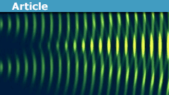
An important topic in diffraction-limited optics is the Airy Disk, which is defined as "the best focused spot of light that a perfect lens with a circular aperture can make, limited by the diffraction of light." The diameter of the Airy disk's first rings drive requirements in many optical imaging systems like cameras, telescopes, infrared imagers, etc.
Airy disk, intensity profile:
View attachment 197155
A useful equation for use in optical and imaging system engineering is the "Airy Disc Diameter," also described as the diameter to the first "intensity zero," and is useful for estimating the smallest resolvable feature in an image.
Airy Disc Diameter:
[tex]D=2.44*λ*f_{number}[/tex]
Where:
D = Diameter to first intensity zero (microns)
λ = Working wavelength (microns)
f_number = Working f-number of the optical system
This equation can be simplified further with some approximations for visual imaging systems. If we assume the image is primarily green (~546 nm, 0.546 microns), the equation simplifies to:
[tex]D_{546nm}=1.33*f_{number}[/tex]
Given this simplified version, we can see that imaging performance of a visible camera for example is driven by f/#, where a "faster" f/# (a.k.a. numerically lower) optical system (like a well-designed SLR camera lens) will give better diffraction-limited resolution. As a general rule, a digital camera's sensor will need pixels which are on the order of size of the airy disc diameter for the lens being used. Many modern cameras (especially cell phone cameras) are limited in resolving power due to the lens's f/#, rather than the pixel count on the image sensor.@Mech_Engineer I'm glad you liked the article. The Airy disc I believe is what you get for the shape and intensity of the focused diffraction spot if you assume a circular aperture. The result that I have in the article above results from assuming a square aperture. It is a somewhat specialized topic so that it hasn't received a tremendous number of views, but I'm so glad you found it interesting. :) :)
This is a cool article!
Some additional info which might be useful:
An important topic in diffraction-limited optics is the Airy Disk, which is defined as "the best focused spot of light that a perfect lens with a circular aperture can make, limited by the diffraction of light." The diameter of the Airy disk's first rings drive requirements in many optical imaging systems like cameras, telescopes, infrared imagers, etc.
Airy disk, intensity profile:
View attachment 197155
A useful equation for use in optical and imaging system engineering is the "Airy Disc Diameter," also described as the diameter to the first "intensity zero," and is useful for estimating the smallest resolvable feature in an image.
Airy Disc Diameter:
[tex]D=2.44*λ*f_{number}[/tex]
Where:
D = Diameter to first intensity zero (microns)
λ = Working wavelength (microns)
f_number = Working f-number of the optical system
This equation can be simplified further with some approximations for visual imaging systems. If we assume the image is primarily green (~546 nm, 0.546 microns), the equation simplifies to:
[tex]D_{546nm}=1.33*f_{number}[/tex]
Given this simplified version, we can see that imaging performance of a visible camera for example is driven by f/#, where a "faster" f/# (a.k.a. numerically lower) optical system (like a well-designed SLR camera lens) will give better diffraction-limited resolution. As a general rule, a digital camera's sensor will need pixels which are on the order of size of the airy disc diameter for the lens being used. Many modern cameras (especially cell phone cameras) are limited in resolving power due to the lens's f/#, rather than the pixel count on the image sensor.
One additional input is the stars are far enough away that the light from them is collimated and thereby the focused spot size that occurs with a perfectly paraboidal primary telescope mirror (neglecting atmospheric turbulence) is diffraction limited in size. The stars are far enough away that they are essentially point sources at infinity, but the image size in the focal plane of the primary mirror of the telescope is larger than a point and is determined by the diffraction limited spot size.