
Parallel Programming on a CPU with AVX-512
This article is the second of a two-part series that presents two distinctly different approaches to parallel programming. In the two articles, I use different approaches to solve the same problem: finding the best-fitting line (or regression line) for a set of points.
The two different approaches to parallel programming presented in this and the preceding Insights article (Parallel Programming on an NVIDIA GPU | Physics Forums) use these technologies.
- Single-instruction multiple-thread (SIMT) programming is provided on the Nvidia® family of graphics processing units (GPUs). In SIMT programming, a single instruction is executed simultaneously on hundreds of microprocessors on a graphics card.
- Single-instruction multiple data (SIMD) as provided on x64 processors from Intel® and AMD® (this article). In SIMD programming, a single instruction operates on wide registers that can contain vectors of numbers simultaneously.
In this article, I describe a program that uses Intel AVX-512 assembly instructions and includes a comparison of the results from both programs.
Table of Contents
Regression line calculations
Given a set of points (Xi, Yi), where i ranges from 1 to N, the slope m and y-intercept b of the regression line can be found from the following formulas.
$$m = frac{N left(sum_{i = 1}^N X_iY_i right)~ -~ left(sum_{i = 1}^N X_i right) left(sum_{i = 1}^N Y_i right)}{Nleft(sum_{i = 1}^N X_i^2right) – left(sum_{i = 1}^N X_iright)^2 }$$
$$b = frac{sum_{i = 1}^N Y_i – sum_{i = 1}^N X_i} N$$
As can be seen from these formulas, there are many calculations that must be performed. The program must calculate the sum of the x coordinates, as well as the sum of the y coordinates. It must also calculate the sum of the squares of the x coordinates and the sum of the term-by-term xy products. For the latter two sums, it’s convenient to create two new vectors. The first vector consists of the term-by-term products of the x coordinates with themselves. The second consists of the term-by-term product of the x- and y-coordinates.
Similar to the GPU version in the preceding article, the program I’m presenting here uses parallel programming techniques (via the CPU’s AVX-512 assembly instructions) to calculate the term-by-term vector products##< X_i Y_i>## and ##< X_i^2>## . Unlike the GPU version of the program in the preceding article, this program also uses AVX-512 assembly routines to calculate the four sums ##sum X_i##, ##sum Y_i##, ##sum X_iY_i##, and ##sum X_i^2##.
Main program tasks
The main program, written in C, performs the following tasks:
- Declare external (i.e., assembly-coded) functions and declare the arrays and variables that will be used.
- Initialize input vectors.
- Call an assembly routine to calculate the term-by-term product vectors ##<X_iY_i>## and ##<X_i^2>##.
- Call a different assembly routine to calculate the four vector sums ##sum X_i##, ##sum Y_i##, ##sum X_iY_i##, and ##sum X_i^2##.
- Calculate the slope m and y-intercept b of the regression line.
- Display the results of the calculations.
Each of these steps is described in the following sections.
Function prototypes and variable declarations
The two prototypes below inform the compiler that the definitions of sumVector and vecProduct appear elsewhere in the project (in a separate file). These two functions are written in pure assembly code, with much of it in AVX-512 assembly code.
The four arrays declared below represent the vectors ##<X_i>, <Y_i>, <X_i^2>,## and ##<X_iY_i>##. The first two vectors are, respectively, the x- and y-coordinates of 262,144 points. The four arrays are aligned on 64-byte boundaries, as required by the relevant AVX-512 instructions.
// Prototypes for assembly routines.
extern "C" double sumVector(double[], int);
extern "C" void vecProduct(double output[], double arr1[], double arr2[], int count);

const int NUMELEMENTS = 512 * 512;
// Allocate the input vectors X, Y, XY, XX
__declspec(align(64)) double X[NUMELEMENTS];
__declspec(align(64)) double Y[NUMELEMENTS];
__declspec(align(64)) double XX[NUMELEMENTS];
__declspec(align(64)) double XY[NUMELEMENTS];
Input vector initialization
To make things simple, the program generates points that lie on a line. Doing things this way makes it simple to confirm that the calculated slope and y-intercept of the regression line are correct. In the code below that initializes the two coordinate vectors, I have “unrolled” the loop by calculating four sets of points per loop iteration, rather than doing just one pair of coordinates at a time.
// Initialize the input vectors.
// All points lie on the line y = 1*x + 0.5.
const double slope = 1.0;
const double y_int = 0.5;

for (int i = 0; i < NUMELEMENTS; i += 4)
{
    X[i] = slope * i;
    Y[i] = X[i] + y_int;
    X[i+1] = slope * (i+1);
    Y[i+1] = X[i+1] + y_int;
    X[i+2] = slope * (i+2);
    Y[i+2] = X[i+2] + y_int;
    X[i+3] = slope * (i+3);
    Y[i+3] = X[i+3] + y_int;
}
Calls to vecProduct
At this point the two input vectors have been initialized with 262,144 (= 512 X 512) points. After vecProduct returns in the first line, XY will contain the term-by-term products of the corresponding elements of the X and Y vectors.
The second call to vecProduct will set the vector XX similarly.
// Calculate vector product X*Y.
vecProduct(XY, X, Y, NUMELEMENTS);

// Calculate vector product X*X.
vecProduct(XX, X, X, NUMELEMENTS);
Calls to sumVector
The calculation of the regression line parameters also requires four vector sums: ##sum X_i##, ##sum Y_i##, ##sum X_iY_i##, and ##sum X_i^2##.
double sumX = 0;
sumX = sumVector(X, NUMELEMENTS);
The other three sums are calculated in a similar fashion.
Slope and intercept calculations
After all four vector sums are calculated, it’s a simple matter of plugging them into the formulas for the slope (m) and y-intercept (b) of the regression line.
m = (double)(NUMELEMENTS * sumXY - sumX * sumY) / (NUMELEMENTS * sumXX - sumX * sumX);
b = (double)(sumY - sumX) / NUMELEMENTS;
Display the results
Rather than showing the code that displays the results, I’ll just show the program output. The last four lines are a sanity check: a comparison of the computed values for the slope and y-intercept against the know values of these line parameters.
[Linear regression of 262144 points]
Sum of x: 34359607296.000000
Sum of y: 34359738368.000000
Sum of xy: 6004782323269632.000000
Sum of x^2: 6004765143465984.000000
Processed 262144 points
Predicted value of m: 1.000000
Computed value of m: 1.0000000000
Predicted value of b: 0.500000
Computed value of b: 0.5000000000
Assembly code
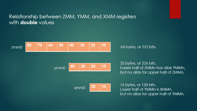
A note on AVX-512 registers
An AVX-512 register such as ZMM0 is 64 bytes or 512 bits wide and can contain a vector of 8 double values, 16 float or int values, 32 short values, or 64 char values. Its lower half of ZMM0, which contains 32 bytes, has an alias of YMM0. In contrast, the upper half of any ZMM register does not have an alias. Similarly, the lower half of YMM0 has an alias of XMM0, but the upper half of any YMM register does not have an alias. Figure 1 shows the relationships between ZMM, YMM, and XMM registers.
Data section
The data section defines storage for STRIDE. This is used to increment the source and destination index registers RSI and RDI by the number of bytes in 8 values of type double (64 bytes).
.data

STRIDE dq 64
vecProduct routine
The vecProduct routine takes two vectors as input and stores the term-by-term products in a third vector.
vecProduct PROC C
    ;-----------------------------------------------------------------------------------------------
    ; C prototype: void vecProduct(double * outArr, double * inArr1, double * inArr2, int array_len)
    ; The vecProduct proc calculates the term-by-term products of the elements
    ; of inArr1 and inArr2, and stores the products in outArr.
    ;
    ; Input args:
    ;     outArr - address of output array, passed in RCX.
    ;     inArr1 - address of first input array, passed in RDX.
    ;     inArr2 - address of second input array, passed in R8.
    ;     arr_len - number of elements of each array, passed in R9.
    ; Return value: None.
    ; On return, RAX holds the address of the vector product.
    ; In each iteration, 8 doubles are read from memory and stored in ZMM1,
    ;   and the next 8 doubles are read from memory and stored in ZMM2.
    ;-----------------------------------------------------------------------------------------------

; Prologue
    push rdi         ; RDI is a non-volatile register, so save it.
    sub rsp, 20h
    mov r10, rsp
    push rsi          ; Save RSI as well.

; Initialization
    vzeroall          ; Zero out all ZMM registers.
    mov rax, rcx      ; Copy output array address to RAX.
    shr r9, 3         ; r9 <- Number of octets of doubles.
    mov rcx, r9       ; Copy no. of 16-float chunks to RCX
    xor rsi, rsi      ; Zero RSI.
    xor rdi, rdi      ; Zero RDI.
    vorpd xmm3, xmm3, xmmword ptr [HIMASK] ; Set bits in lower half of XMM3 for later use.

ProcessChunks:
    ;-----------------------------------------------------------------------------------------------
    ; Iterate through both arrays, doing term-by-term multiplication.
    vmovapd zmm1, zmmword ptr [rdx + rsi]    ; Store 8 doubles from first array to ZMM1.
    vmovapd zmm2, zmmword ptr [r8 + rsi]     ; Store 8 doubles from second array to ZMM2.

    ; Do term-by-term multiplication of ZMM1 and ZMM2, storing result in ZMM1.
    vmulpd zmm0, zmm1, zmm2                  ; ZMM0 = ZMM1 * ZMM2

    ; Store products from previous loop iteration into output array memory.
    vmovapd zmmword ptr[rax + rdi], zmm0
    add rsi, STRIDE           ; Advance 8 doubles (64 bytes) higher in first array.
    add rdi, STRIDE           ; Advance 8 doubles (64 bytes) higher in second array.
    loop ProcessChunks
    ;-----------------------------------------------------------------------------------------------

; Epilogue
    pop rsi              ; Restore RSI.
    mov rsp, r10
    add rsp, 20h         ; Adjust the stack back to original state.
    pop rdi              ; Restore RDI.
    ret
vecProduct ENDP
How vecProduct works
Of the two assembly routines, vecProduct is a lot simpler to explain. The first and last sections, labelled Prologue and Epilogue, are boilerplate sections of code that are required in 64-bit assembly routines. Suffice it to say that they just set aside some stack memory and then later reclaim it.
Initialization section
The Initialization section zeroes all of the 512-bit ZMM registers, and copies the output and input vector addresses from the registers used to pass them into different registers. It also sets up the RCX register to the number of iterations of a loop that will be used to process all of the values in the input vectors. The loop will multiply 8 values of type double from each of the two input vectors in each iteration, and store the result in the output vector. For this reason, RCX is set to the number of double octets (64 bytes or 512 bits from each input vector) that must be processed.
ProcessChunks section
In the ProcessChunks section, the code copies (moves) 8 double values to ZMM1, and then copies 8 more to ZMM2. These instructions use a pair of AVX-512 instructions, vmovapd. (Note that the main purpose of this instruction is to move values from one place to another.) Many of the AVX-512 instructions have a v prefix, which indicates that they work on vectors of numbers, as opposed to single numbers. The apd suffix is an abbreviation for aligned (memory), packed double.
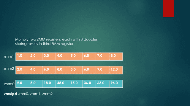
The 8 double values in each of ZMM1 and ZMM2 are multiplied pairwise using the vmulpd instruction (a multiply operation), with the results being placed in ZMM0. Again, the pd suffix is short for packed double. Figure 2 shows the results of the vmulpd instruction, multiplying each corresponding double in the two source registers, with the results being stored in ZMM0.
The results in ZMM0 are then copied to the memory for the output vector using vmovapd again, where the output vector’s base destination address is in RAX.
After this, the index registers RSI and RDI are incremented by STRIDE (64 bytes, the size of 8 doubles), and the loop instruction decrements RCX by 1. Control flows back to the first instruction after the ProcessChunks label, provided that RCX is still nonzero. When RCX finally gets to zero, control drops through to the next line after the loop instruction.
When vecProduct completes execution, RAX holds the address of the vector of element-by-element products of the two input vectors.
sumVector routine
The sumVector routine sums all of the elements of its input vector and returns this sum as a double value.
sumVector PROC C
    ;-----------------------------------------------------------------------------------------------
    ; C prototype: float sumVector(double * inputArray, int array_len)
    ; The sumVector proc adds the elements of a passed array.
    ; Parameters
    ;     inputArray - address of an array of doubles, passed in RCX
    ;     array_len - number of elements of inputArray, passed in RDX
    ; Return value
    ; Returns the sum of the elements in the passed array in XMM0.
    ; In each loop iteration, zmm1 is set with 8 doubles.
    ;-----------------------------------------------------------------------------------------------

; Prologue
    push rdi ; RDI is a non-volatile register, so save it.
    sub rsp, 20h
    mov rdi, rsp
    push rsi ; RSI also needs to be saved.

; Initialization
    vzeroall ; Zero out all ZMM registers
    mov rax, rcx ; Copy array address to RAX.
    mov rcx, rdx ; Copy element count to RCX.
    shr rcx, 4 ; RCX <- Number of 2 X 8-double chunks.
    xor rsi, rsi ; Zero RSI.

PartialSumsLoop:
    ;-----------------------------------------------------------------------------------------------
    ; In each iteration, accumulate 8 partial sums of doubles.
    ; When loop terminates, ZMM0 will hold 8 doubles that,
    ; when added, will be the overall sum of the given array.
    vmovapd zmm1, zmmword ptr [rax + rsi] ; Get 8 doubles and store in ZMM1.
    vaddpd zmm0, zmm0, zmm1 ; ZMM0 = ZMM0 + ZMM1.
    add rsi, STRIDE
    vmovapd zmm4, zmmword ptr [rax + rsi] ; Get 8 more doubles and store in ZMM4.

    ; Accumulate sum from previous loop iteration.
    vaddpd zmm0, zmm0, zmm4 ; ZMM0 = ZMM0 + ZMM4.
    add rsi, STRIDE ; Increment RSI to advance to next block of 8 doubles in the array.
    loop PartialSumsLoop
    ;-----------------------------------------------------------------------------------------------

CombineSums:
    ; Use vextractf64x4 to extract 4 doubles (256 bits) from the upper half of ZMM0 to YMM1.
    ; YMM0 already contains the lower 256 bits (four doubles) of ZMM0.
    vextractf64x4 ymm1, zmm0, 1
    vaddpd ymm1, ymm1, ymm0 ; YMM0 <-- YMM1 + YMM0.
    ; Assuming YMM0 contains y3, y2, y1, y0, and YMM1 contains x3, x2, x1, x0,
    ; YMM1 now contains as qwords y3+x3, y2+x2, y1+x1, y0+x0

    ; Use horizontal addition. I'm not aware of any version of vhaddpd for AVX-512.
    ; So I'm limited to working with YMM registers, but not ZMM registers.
    vhaddpd ymm1, ymm1, ymm1
    ; After vhaddpd, YMM1 now contains as qwords y3+x3+y2+x2 (two times), y1+x1+y0+x0 (two times).

    vmovapd ymm2, ymm1 ; Copy qwords in YMM1 to YMM2

    ; Permute the bits in ymm2, essentially shifting the quadword at index 2 to index 0,
    ; with all other indexes left unchanged. After permutation,
    ; YMM2 will contain y3+x3+y2+x2 at index 0, and YMM1 still has y1+x1+y0+x0 at index 0.
    ; Indexes 1, 2, and 3 are don't care.
    vpermpd ymm2, ymm2, 2

    ; Add YMM1 and YMM2, storing result in YMM0.
    vaddpd ymm0, ymm1, ymm2

    ; At this point, YMM0's lower half, i.e., XMM0, is ready to be returned. Its lower half, a double,
    ;    which is what the caller of this routine is expecting, contains the sum of all elements of the input vector.
; Epilogue
    pop rsi
    add rsp, 20h      ; Adjust the stack back to original state
    pop rdi           ; Restore RDI
    ret
    sumVector ENDP
How sumVector works
The sumVector routine is quite a bit more difficult to describe because adding the elements of a ZMM register is not as simple as pairwise arithmetic on two such registers.
Prologue and Epilogue sections
As was the case with the previously described vecProduct routine, the Prologue and Epilogue sections are boilerplate. The descriptions are similar to those for vecProduct.
Initialization section
The section with the label Initialization takes care of necessary chores, such as moving values from the input registers to other registers and initializing the AVX-512 registers.
PartialSumsLoop section
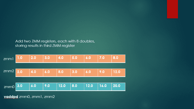
The code in the section marked PartialSumsLoop cycles through the vector being summed, working with 16 double values in each loop iteration, using two ZMM registers. The code accumulates 16 double values into register ZMM0. Instead of working with only 8 double values per loop iteration, I am “unrolling” the loop slightly in the interest of keeping the instruction pipeline as full as possible. Figure 3 below provides a visual explanation of how the 16 double values are added to the register that is acting as the accumulator. The loop is finished when the RCX register finally reaches zero.
After the program exhausts all of the elements of the vector to be summed, a 512-bit ZMM register contains 8 partial sums. The next step is to add these 8 double values to get the grand total. Oddly enough, this is not a straightforward matter, mostly due to the lack of an instruction that can add all 8 double values in a 512-bit ZMM register. Fortunately, there is an instruction that can work with the 4 double values in a 256-bit YMM register.
CombineSums section
There is a lot of action going on in the CombineSums section.
- Carry out a partial addition by reducing the number of values to be added.
- Perform horizontal addition to get a double that contains the sum of all elements of an input vector.
- Set up the XMM0 register with the routine’s return value, namely the double result in its lower 64 bits.
The following subsections describe each of these larger steps.
Shrink the number of values to be added
The section marked CombineSums carries out the steps necessary to add the 8 partial sums mentioned in the previous section.
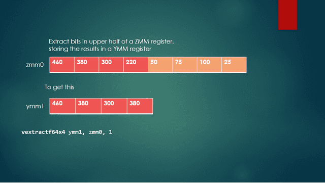
The first step is to split up the 8 double values in ZMM0 between two YMM registers, with 4 double values in the YMM0 register, and 4 more in the YMM1 register. Part of the work is already done because the lower half (lower 256 bits) of ZMM0 is aliased as YMM0. The code uses the vextractf64x4 instruction to extract the 4 double values from the upper half (index 1) of ZMM0, placing them into YMM1. The f64x4 suffix means that 4 floating-point 64-bit values (i.e., 4 double values) are to be extracted. The third operand here, 1, indicates the upper half of the ZMM register. An operand of 0 would mean that we wish to extract the values in the lower half. Figure 4 below depicts the operation of this instruction, with YMM1 as shown, and YMM0 being the lower half of ZMM0 (in orange).
After the code splits up the 8 partial sums into 4 partial sums each in the YMM0 and YMM1 registers, the next step is to add these two registers together, using the vaddpd instruction. This means that the program now needs to add only four elements of a YMM register, rather than the eight elements of a ZMM register to get the same grand total. The left portion of Figure 5 shows the action of vaddpd, with the 4 elements each of registers YMM1 and YMM2 being added and then stored in YMM0. The permute portion of Figure 5 will be discussed later.
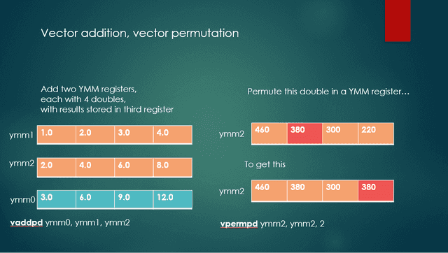
Perform horizontal addition
At this point, the 4 partial sums that make up the grand total are in register YMM1. The program then uses the vhaddpd instruction to perform a horizontal addition of YMM1 with itself, with the results stored in YMM1. The middle part of the instruction name, hadd, is short for horizontal addition.
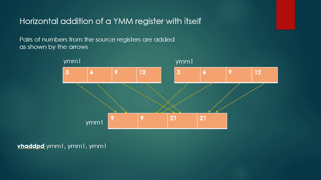
From the upper left YMM instance, this operation takes the two left-most double values, adds them, and stores this value at index 3 in the bottom YMM instance. From the upper right YMM instance, the operation takes the two left-most values, adds them, and then stores exactly the same value at index 2 in the bottom YMM instance. The two lowest values in the upper left YMM instance are added and then stored at index 1 in the lower YMM instance. The two lowest values in the upper right YMM instance are added and then stored at index 0 in the lower YMM instance. Because the program is performing horizontal addition on a register with itself, the two values at indexes 3 and 2 at the bottom are identical, as are those at indexes 1 and 0.
Let’s take a moment to think about what’s happening here. The goal is to add, say, 3 + 6 + 9 + 12, which sums to 30. After the horizontal addition, YMM1 contains 9, 9, 21, and 21, reading from left to right. If we can somehow add the 9 and 21, we’ll have our correct sum, namely 30.
Set up the XMM0 return value register
If you’re still with me, congratulations! We’re almost done! At this point, YMM1 contains <9, 9, 21, 21>, reading left to right. The only steps remaining are:
- Copy YMM1 to YMM2, using the instruction vmovapd ymm2, ymm1. Therefore, YMM1 contains <9, 9, 21, 21> as does YMM2.
- Permute the bits in YMM2 so that the double at index 2 ends up at index 0. The code does this by using the instruction vpermpd ymm2, ymm2, 2, which is depicted in the right half of Figure 4. As I have used it in the program, this permutation really is more of a shift operation. The instruction merely shifts the 64 bits at index 2 of YMM2 to index 0, leaving the other three double values unchanged.
YMM1 is still <9, 9, 21, 21> but YMM2 is now <9, 9, 21, 9>. - Add YMM1 and YMM2, with the result being written to YMM0, using vaddpd ymm0, ymm1, ymm2. The result of this action is that YMM0 is <18, 18, 42, 30>. Note that the sum we wanted is now at index 0 in YMM0.
Remember that I said that adding the components of a vector was a complicated operation!
The lower half of YMM0 is also known as XMM0, which is <42, 30>, with 42 in the upper half of XMM0 and 30 in the lower half of XMM0.
When sumVector completes execution, it returns the sum of all elements of the input vector in XMM0. However, since the caller is expecting only the double that is in the lower half of XMM0, any value that might be present in the upper half of XMM0 is invisible to the caller.
Timing comparisons – CUDA vs. AVX-512
All vectors used in the two programs consisted of 262,144 elements of type double, with both programs compiled in Release mode.
For timing, I used the high_resolution_clock::time_point class of the chrono namespace, which has a resolution as small as 1 nanosecond. I don’t show the code I used, but if you’re interested, follow the link at the end of this article to my Github repository.
I ran both programs on a Dell Precision 7820 computer, with an Intel Xeon(R) Silver 4144 CPU. The nominal clock rate is 2.20 GHz. The CPU has 10 cores, but I did not attempt to take advantage of the multiple cores.
I ran the CUDA version on the NVidia Quadro P2000 GPU (Pascal architecture). This GPU has 8 multiprocessors with a total of 1024 cores and has 5120 MB of global memory. The card’s GPU clock rate is 1481 MHz, and its memory clock rate is 3504 MHz.
Calculate term-by-term vector products
The following table contains the combined times for the term-by-term vector products ##< X_iY_i>## and ##< X_i^2>## for six runs of the CUDA code and the AVX-512 code. All times are in microseconds.
| CUDA (usec.) | AVX-512 (usec) |
|---|---|
| 5688 | 4264 |
| 5468 | 6873 |
| 2804 | 3959 |
| 5586 | 3597 |
| 2745 | 3990 |
| 5632 | 4194 |
| Average: 4653.8 microseconds | Average: 4479.5 microseconds |
These results surprised me. I thought that the AVX-512 code would be greatly outperformed by the CUDA code, but in most of the runs, that was not the case. The likely reason for how much time the CUDA code took is that a lot of the overall time is expended in copying vectors from host memory to device memory and then copying them back from device memory to host memory. The bottleneck is likely these memory transfers.
Calculating vector sums
The following table contains the combined times for the four vector sums ##sum X_i##, ##sum Y_i##, ##sum X_iY_i##, and ##sum X_i^2##, for six runs of the CUDA code and the AVX-512 code. All times are in microseconds.
| CUDA (time in usec.) | AVX512 (time in usec) |
|---|---|
| 1463 | 654 |
| 1624 | 852 |
| 698 | 640 |
| 1519 | 616 |
| 724 | 640 |
| 1615 | 665 |
| Average: 1273.8 microseconds | Average 677.8 microseconds |
The CUDA program was at a disadvantage in calculating the vector sums because it used the CPU to calculate the sums rather than the GPU.
Complete code
For the sake of brevity, I haven’t included the complete source code here in this article. If your curiosity is piqued, and you are a glutton for punishment, you can find the source code for this article, Main2.cpp, and avxTest.asm here: https://github.com/Mark44-AVX/CUDA-vs.-AVX-512.
Former college mathematics professor for 19 years where I also taught a variety of programming languages, including Fortran, Modula-2, C, and C++. Former technical writer for 15 years at a large software firm headquartered in Redmond, WA. Current associate faculty at a nearby community college, teaching classes in C++ and computer architecture/assembly language.
I enjoy traipsing around off-trail in Olympic National Park and the North Cascades and elsewhere, as well as riding and tinkering with my four motorcycles.


I’m very interested in hearing comments or questions about this article or the other article in this set — [URL]https://www.physicsforums.com/threads/parallel-programming-on-an-nvidia-gpu.1014468/[/URL].