Lewin’s Circuit Paradox: Distinguishing E_s and E_m
Table of Contents
Introduction
Much has lately been said regarding this paradox that first appeared in one of W. Lewin’s MIT lecture series on YouTube (see References [1]). This lecture was critiqued by C. Mabilde in a second YouTube video and submitted as a post in a Physics Forums thread (see References [2]). The latter cited a third source, K. T. McDonald of Princeton University, as support for Mabilde’s presentation (see References [3], [4]). Finally, Charles Link (PF Homework Helper and Insight Author) posted in Advisory Lounge Inner Circle (#1, May 25, 2018) on the same subject. Several other PF members (and probably others) have been involved in this topic.
Two electric fields: E_s and E_m
I think a key concept, which none of the three sources explicitly mentions, is that there are two E fields present. One is the static (conservative) field E_s, whose field lines begin and end on charges. The second is the emf-induced (non-conservative) field E_m, whose circulation can be non-zero. E_m can be created by a chemical battery, magnetic induction, the Seebeck effect, and other emf sources.
In the case of Faraday induction, the circulation of E_m is Faraday’s ##\frac{-d\phi}{dt}##. In a loop that contains ideal (zero-resistance) wires and localized resistors, the two fields algebraically sum everywhere: ##E = E_s + E_m##. The two fields can cancel each other in wire segments; however, inside resistors only the conservative field E_s exists (this statement assumes negligible resistor body lengths and zero-resistance wires outside the resistors).
What a voltmeter measures
A voltmeter reads the line integral of E_s between its probe points, not the circulation associated with E_m. This distinction explains many apparent paradoxes when emf sources are present in a circuit.
Battery example (Lewin’s battery setup)
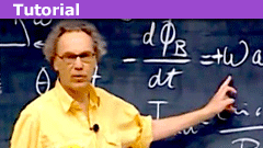
For example, in his battery setup (Fig. 1) Dr. Lewin assumes a net battery E field opposite to the direction of the E field in the resistor. In fact the battery contains two canceling field contributions: E_s points + to − and E_m points − to +. The line integral of E_m over the battery (- to +) is the battery emf. A voltmeter senses only the line integral of E_s; otherwise a DC voltmeter directly across a battery would read 0 V. In the resistor E_s points + to −; the circulation of E_s around the loop is zero as required by Kirchhoff’s voltage law. The circulation of E_m, and thus of the net E, equals ##iR## (with ##i## the current and ##R## the resistor).*
Solenoid and single-turn loop (voltmeters placed near the loop)
Now to address the main topic — the solenoid, the single-turn loop, and voltmeters positioned as shown in Fig. 2 — assume again that the loop wires have negligible resistance.

Definitions
- ##\phi## = magnetic flux inside the loop
- loop radius = ##a##
- loop current = ##i##
- total loop induced emf = ##\oint \mathbf{E_m}\cdot\mathbf{dl}##
Hence,
$$ E_m = \frac{\frac{-d\phi}{dt}}{2\pi a}. $$
Around the loop (with or without resistors ##R1## and ##R2##) a continuum of E_m exists and an opposing E_s runs in the opposite direction. Inside the resistors E_s can be large because ##E_s = iR/d## with ##d## the length of each resistor and ##d \ll 2\pi a##. All of this follows from ##\oint\vec E_s\cdot d\vec l = 0##; the line integral of the resistors’ E_s fields equals the scalar emf ##\mathcal{E}## and is canceled around the loop by wire-segment E_s fields.
Why a voltmeter placed on a wire section reads zero
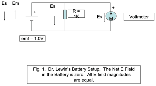
Next, show that a voltmeter connected at two points a and b along the loop that do not include a resistor reads 0 V (Fig. 3). Although this can seem paradoxical, it is consistent once the two-field picture is used.
First, remember that in an ideal conductor the net electric field must vanish. Thus in the wire segments (including the shorter section a–b and the meter leads) the conservative and emf-induced fields must be equal in magnitude and opposite in sign.
Voltmeter model and notation
- ##E_{mw}## = the emf-induced field in the meter leads
- ##E_{sw}## = the static (conservative) field in the meter leads
- ##E_{sv}## = the static field in the voltmeter
- ##E_{mv}## = the emf-induced field in the voltmeter
- ##l_w## = the total meter lead length
Model the voltmeter as a resistor of finite physical length ##d## with resistance ##r##, carrying a tiny current ##i_v##. The meter reads ##i_v\cdot r##. Because ##E_{sv}## and ##E_{mv}## oppose each other inside the meter,
$$ i_v\cdot r = (E_{sv} – E_{mv})\cdot d, $$
or equivalently
$$ d\cdot E_{sv} = i_v\cdot r + d\cdot E_{mv}. $$
Now perform the circulation of E_s around the meter circuit:
## +E_{sw}\cdot l_w + i_v\cdot r + E_{sv}\cdot d \;-\; E_s \theta a \;=\; 0. ##
The circulation of E_m around the same contour is zero if there are no emf sources inside/around that contour:
## E_{mw}\cdot l_w + d\cdot E_{mv} \;-\; E_m \theta a \;=\; 0. ##
Combining these, and using that inside ideal conductors the two field components match in magnitude (so the meter lead magnitudes satisfy ##E_{sw}=E_{mw}## and the wire segment magnitudes satisfy ##E_s=E_m##), one finds
## i_v\cdot r = 0 \Rightarrow i_v = 0 \Rightarrow \text{VM} = 0. ##
Thus VM = 0 for an uninterrupted wire segment of the loop. If the voltmeter probes a length of wire with a resistor ##R## in-between, the voltmeter reads VM = ##iR##, independent of the lengths of the surrounding wire segments. This result includes Lewin’s A and D probe points at the top and bottom of the loop illustrated in Figs. 2 and 3.
Scalar potential versus measured voltmeter reading
We therefore distinguish between voltmeter readings (what a physical meter measures) and the scalar-potential difference defined as ##\int \mathbf{E_s}\cdot d\mathbf{l}##. McDonald rightly notes that meter lead coupling accounts for differences between measured voltages and scalar potentials; this is why he argues for accepting scalar-potential differences as the “true” potential difference, not subject to measurement detail. Mabilde’s demonstration is a valid experimental method to obtain the scalar potential: his interior voltage-measuring setup reproduces the scalar potential by effectively sampling the E_s field profile established around the ring by the meter lead geometry.
His criticism of Lewin’s “Kirchhoff was wrong” claim is also appropriate if we understand that Kirchhoff’s voltage law applies only to voltages in the correct sense (line integrals of E_s) and does not apply to E_m fields.
Further remarks and a quantitative example
I emphasize that voltmeter readings in Lewin’s setup can be entirely accounted for without splitting the E field into E_m and E_s. The split is, however, useful for insight: it explains the difference between meter readings and scalar-potential differences. It is not merely meter lead dressing; any meter loop in any orientation will give the same coupling results. The effect is simply sharing of E_m and E_s between the main loop and the meter loop. As McDonald notes, to avoid coupling effects the meter probes should be connected directly at a resistor; otherwise scalar-potential measurements will miss contributions associated with loop wiring.
Lewin did not, to my recollection, place the VM leads in the middle of the solenoid. If he had, the reading would be halfway between −0.1 V and +0.9 V, i.e. +0.4 V. Reflecting on the numerical mismatch between expected and actual VM readings: the R1 meter reading was −0.1 V − 0.4 V = −0.5 V (too negative), while for the R2 loop it was +0.9 V − 0.4 V = +0.5 V (too positive). If we integrate the E_s field over the meter loop with the meter positioned halfway above the solenoid, the line-integral sum gives
## \mathcal{E}/2 – iR2 + \text{VM} = 0 \quad\Rightarrow\quad \text{VM} = +0.4\text{ V}. ##
Or, equivalently,
## -\text{VM} + \mathcal{E}/2 – iR1 = 0, ##
which also yields VM = +0.4 V and agrees with the data. Suspending the voltmeter with its leads directly above the magnetic source gives the expected voltage.
Conclusion
To summarize: be aware of two separate electric-field contributions in loops with emf sources — the non-conservative E_m (emf-induced) field and the conservative E_s (scalar-potential) field. Voltmeters can give readings that differ from scalar-potential differences when the meter circuit forms an alternate path for the E_m field, as in Lewin’s setup. Coupling effects are predictable: they are simply E_m and E_s sharing between the primary loop and the meter loop. Spurious coupling must be identified and avoided to obtain actual scalar-potential differences; this can be nontrivial in practice.
Failure to recognize the two types of field leads to confusion or apparent violation of circuit laws in any circuit containing one or more emf sources (batteries, induction, etc.).
See also H. H. Skilling, Fundamentals of Electric Waves (Stanford Professor Emeritus), available online.
* Footnote (added 09/12/2018): Since the circulation of the E_m field equals ##iR##, by Stokes’s theorem there must exist net curl within the contour. If we set up x-y-z coordinates with the contour in the x-y plane and the x-axis at the negative terminal of the battery, y-axis just inside the battery on its right-hand side, and L the battery length from negative to positive terminal, then
## iR = \oint \vec E_m\cdot d\vec l = \iint_S (\nabla\times\vec E_m)\cdot d\vec A. ##
A curl that satisfies this is ## \nabla\times\vec E_m = \frac{\partial E_m}{\partial x}\,\mathbf{k} = E_m\delta(x)\,\mathbf{k}. ## Then
## \iint_S (\nabla\times\vec E_m)\cdot d\vec A = \int_{0^-}^{L^+} E_m L \,\delta(x)\,dx = E_m L, ## as expected.
References
- https://www.youtube.com/watch?v=FUUMCT7FjaI
- https://www.physicsforums.com/threads/faradays-law-circular-loop-with-a-triangle.926206/page-4
- Attachment: K. McDonald: “Lewin’s Circuit Paradox”
- Attachment: K. McDonald, “What Does a Voltmeter Measure?”
AB Engineering and Applied Physics
MSEE
Aerospace electronics career
Used to hike; classical music, esp. contemporary; Agatha Christie mysteries.


BTW Contrary to the statement in the above cited Insight article, of course there are both electric and magnetic fields in stationary circuits (in fact there's only one electromagnetic field in nature, but that's another story)..E[SUB]m[/SUB] is also an electric, not a magnetic field. Two E fields: E[SUB]s[/SUB] and E[SUB]m[/SUB]. One begins and ends on charges; the other does not.
@vanhees71 makes a very good point, you can no longer use the term "voltage" when you include a circuit loop that has a changing magnetic field inside of it. ## \ ## The "voltmeter" does not measure a "voltage" difference in this case, between the two points on the circuit that it probes.## \ ## Instead, the voltmeter needs to be considered for what it actually is=a couple of wires with a large resistor through which a small current flows. In this case, the voltmeter really doesn't "measure". Instead, it gives a reading which is the (multiplicative) product of the small current times the large resistor. The placement of the wires that form the leads of the voltmeter can yield different results depending on whether the circuit loop that they form encloses the changing magnetic field, in which case there is an EMF around that circuit loop.Yes. Your resistive voltmeter shows the field equivalent of Ohm's law which is ir = d(E[SUB]s[/SUB] + E[SUB]m[/SUB]) with d the length of r. This reduces to ir = dE[SUB]s[/SUB] if d << voltmeter wire lead lengths. In my various posts I had made this assumption.
There is no paradox whatsoever!. I admit, it took me a while to understand what is going on.
First thing first, the loop with two resistor is a red hearing. So, let's remove it and we get a circuit like that:
View attachment 237904
Now, we have a loop containing two voltmeters encircling flux change of 1 Wb/s. Obviously, the induced EMF is 1 Volt and the direction is indicated by the circular arrow. With the way the voltmeters are connected, the one on the right would show a positive voltage, the other negative voltage, just like in the video.
How much will each of them show?. That would depend on the internal resistance of the voltmeters. Portable meters have resistance of 10 Mohm, if both have this value, one will show 0.5 V, the other -0.5 V. Change the internal resistance of the left voltmeter to 1 Mohm and the other one to 9 Mohm and you will get -0.1 v and 0.9 V. No paradox, just a red herring.
However, Dr Lewin makes a statement in his video that I would disagree. He says that the Kirchhoff (second) law is not valid. The way I was thought physics, it is still valid. I understand that the Kirchhoff law says that for a loop ##sum I_k R_k = sum EMF## and that actually agrees with the Faraday law.
Now, I would also like to point out that the supposed tutorial contains some false statements. One of the false statement is
"which is non-conservative in the sense that its circulation is non-zero. E[SUB]m[/SUB] can be created by a chemical battery, magnetic induction, the Seebeck effect, and others."
This statement is not correct. The non-conservative electric field can only be created by changing magnetic flux. The field inside a battery is conservative. How is it created.
The key to understand operation of a battery is thermodynamics and equilibrium condition for particle exchange. Thermodynamics tells us that a system is at equilibrium with a reservoir with respect to particle exchange if the chemical potentials are equal. Let's take, for example, an alkaline battery. It consist of a zinc cathode, MnO anode and KOH electrolyte. KOH in solution dissociates into K[SUP]+[/SUP] and OH[SUP]-[/SUP] ions. At the cathode, the following reaction takes place ( see https://en.wikipedia.org/wiki/Alkaline_battery )
Zn(s) + 2OH[SUP]−[/SUP][SUB](aq)[/SUB] → ZnO(s) + H[SUB]2[/SUB]O + 2e[SUP]−[/SUP]
The reaction of solid Zn with OH[SUP]-[/SUP] ions produces ZnO, water and free electrons. Where do the free electrons go? they go to the Zn metal charging it up negatively, i.e. increasing the chemical potential of electrons in the metal. The reaction stops when the chemical potential of electrons in the Zn metal become equal to the chemical potential of the electrons attached to OH[SUP]-[/SUP] ions. The net result is formation of a potential difference at the electrode/electrolyte interface. This is not unlike creation of the depletion layer in a p-n junction of a semiconductor.
Similarly, there is a potential step created at the anode. The total voltage of an (open circuit) battery is algebraic sum of the two voltage steps.
Seebeck effect, photovoltaic cell EMF can also be understood considering the thermodynamics, that is, EMF is created by a gradient of chemical potential of electrons and the field is conservative.
Another equivalent view is that the EMF drives the electrons in the wires making up the volt meter (think of an old-fashioned galvanometer for simplicity), leading to the current @Charles Link mentioned in the previous posting.
This becomes clear if one uses the complete (!) integral form of Faraday's Law of induction. Its fundamental form is, as anything in electromagnetism, the local form in terms of derivatives (SI units):
$$-partial_t vec{B}=mathrm{nabla} times vec{E}.$$
Now if you integrate this over an arbitrarily moving area ##A## with boundary ##partial A## you can first use Stokes's theorem. The only correct version of this simple treatment is
$$-int_{A} mathrm{d}^2 vec{f} cdot partial_t vec{B} = int_{partial A} mathrm{d} vec{r} cdot vec{E}.$$
Now one likes to express in terms of the magnetic flux through the area
$$Phi_{vec{B}}=int_A mathrm{d}^2 vec{f} cdot vec{B}.$$
Now, if the area and its boundary are moving, you cannot take the partial time derivative out of the integral in the previous equation but you get an additional line integral along the boundary curve of the surface, which you can lump to the integral on the right-hand side. Taking Gauß's Law for the magnetic field, ##vec{nabla} cdot vec{B}=0## into account the resulting equation gets
$$-dot Phi_{vec{B}} = int_{partial A} mathrm{d} vec{r} cdot (vec{E}+vec{v} times vec{B})=:text{EMF},$$
where ##vec{v}## is the velocity field along the moving boundary of the area we've integrated over.
Now if you choose the area such that its boundary is along the wires connecting the volt meter with the rest of the circuit, what it measures is in fact the electromotive force, i.e., the line integral along the closed (!) boundary. It's obviously the line integral over the force on a unit charge ##vec{E}+vec{v} times vec{B}##, and this shows that indeed that's the physical picture on what's measured given above: The force on the charges inside the wires connecting the volt meter with the rest of the circuit (including the wires making up the coil in the volt meter, if you take the model of a old-fashioned galvanometer setup).
This considerations also explain why the reading of the volt meter is beyond the simple Kirchhoff circuit theory: It's reading cannot be understood without taking into account the correct geometry of the connection of the volt meter with the rest of the circuit since this you need to calculate the line integral defining the EMF, which is what the volt meter measures. The Kirchhoff theory becomes applicable only if you make the wires connecting the volt meter very short, so that the magnetic flux through the corresponding current loop becomes negligibly small. Then the reading is what you expect according to the Kirchhoff circuit theory, i.e., the EMF through the element of the circuit you want to measure (which may be an Ohmic resistor, a capacitor, or coil).
Note: Another source of confusion is the very name "EMF" for the line integral: Here force is obviously not the modern notion of "force" (which is represented by the Lorentz force per unit charge, ##vec{E}+vec{v} times vec{B}##) but its meaning is more in the sense of "energy". Indeed the EMF is a line integral of the force along a closed loop. The very fact that the quantity is a line integral along a closed loop shows that it is NOT a "voltage". If there'd be a potential for the force integrated over, the integral over any closed loop is 0 (modulo the caveat that the region under consideration is simply connected!).
@vanhees71 makes a very good point, you can no longer use the term "voltage" when you include a circuit loop that has a changing magnetic field inside of it. ## \ ## The "voltmeter" does not measure a "voltage" difference in this case, between the two points on the circuit that it probes.## \ ## Instead, the voltmeter needs to be considered for what it actually is=a couple of wires with a large resistor through which a small current flows. In this case, the voltmeter really doesn't "measure". Instead, it gives a reading which is the (multiplicative) product of the small current times the large resistor. The placement of the wires that form the leads of the voltmeter can yield different results depending on whether the circuit loop that they form encloses the changing magnetic field, in which case there is an EMF around that circuit loop.
Well, there's nothing to fight about. I think there's no paradox at all (I don't like the word "paradox"; it just indicates a lack of careful analysis based on "common knowledge", which is contrary to the very basic principles of basic science). Just use Maxwell's equations, and everything is fine. Also avoid to talk about "voltage" as soon as emf's from time-varying magnetic fields are involved. BTW Contrary to the statement in the above cited Insight article, of course there are both electric and magnetic fields in stationary circuits (in fact there's only one electromagnetic field in nature, but that's another story). The only thing is that one can eliminate them from the considerations using the stated assumptions and lump everything in currents, voltages and emf's. That's because Kirchhoff's laws are nothing else than the integrated version of Maxwell's equations under the simplifying assumptions made.
Pace nobiscum. :cool:
I remember that thread. It got really heated among several people who really know their stuff. You may be right that it's semantics.
I really don't care enough about Professor Lewin to go down that rabbit hole, so I'm going to exit this conversation.
@anorlunda and @rude man I think you both may be arguing the very same thing, and it is open to debate whether the EMF generated in a loop by a changing magnetic field is part of Kirchhoff's voltage laws (KVL), or if it happens to be an exception that Professor Walter Lewin has highlighted. Others have previously argued this fine detail: See https://www.physicsforums.com/threa…ge-across-inductor.880100/page-5#post-5533643 . ## \ ## Right around post 83 @Dale and @vanhees71 went back and forth on this a couple of times, but I think everyone is in agreement on how this problem gets solved, and it is very useful that Professor Walter Lewin has pointed out this special case, even if he says a couple of things that perhaps also aren't 100% accurate.
At minutes 30-35 in the video, he says that Kirchoff's Laws only apply when the external magnetix flux is zero. And since the flux is nonzero in his experiment (assumption #1) you can't use Kirchoff's Laws or circuit analysis to describe that experiment. Well duh. :rolleyes:
Bottom line, you can't say that KVL and KCL apply always.
By the way, be careful when you say you don't agree with those assumptions. They are repeated in many standard textbooks. Peer reviewed journals and standard textbooks are the bible here on PF.Voltage is the line integral of the electrostatic field. And the circulation of that field is zero.
I suggest perusal of the two papers by Princeton's K. McDonald I cited in my Insight article on this subject.
And if I may counter with my own "standard textbook": Fundamentals of Electric Waves by Stanford's H H Skilling. Let me know if you need chapter & pages.
The Lewin setup includes time rate of change of magnetic flux outside a conductor being non-zero if I'm interpreting your statement per your intention, yet there Kirchhoff's laws certainly hold.At minutes 30-35 in the video, he says that Kirchoff's Laws only apply when the external magnetix flux is zero. And since the flux is nonzero in his experiment (assumption #1) you can't use Kirchoff's Laws or circuit analysis to describe that experiment. Well duh. :rolleyes:
Bottom line, you can't say that KVL and KCL apply always.
By the way, be careful when you say you don't agree with those assumptions. They are repeated in many standard textbooks. Peer reviewed journals and standard textbooks are the bible here on PF.
I think I disagree with your #1. The Lewin setup includes time rate of change of magnetic flux outside a conductor being non-zero if I'm interpreting your statement per your intention, yet there Kirchhoff's laws certainly hold.
I agree with the rest. Quasi-stationariness must be assumed, ortherwise lumped-circuit anaylis laws have to be superseded by Maxwell's equations. A radiating circuit is one example, as is a distributed circuit.
But that is not the discussion here.
Reference https://www.physicsforums.com/insights/circuit-analysis-assumptions/
Kirchhoff's laws hold in all cases.That's an overly broad statement. There are important assumptions. If those are violated, then Kirchoff's Laws can not be used. See the Insights Article.
https://www.physicsforums.com/insights/circuit-analysis-assumptions/
I did this experiment and it shows what Dr. Lewin stated. I took a 500 foot roll of wire used for dog fencing. ( it measured 5 ohms). Unspooled it, Cut it in half and rewound 250 feet back on the spool. I brought out a pigtail and connected it to a 1meg resistor. The other end of the resistor went to the 2nd 250 foot wire. I then wound the 2nd piece on the spool in the same direction. and connected a 100 K resistor to the beginning and end of the coil.
I put 2 strong magnets in the center of the coil and snatched them away and got a pulse on my Oscilloscope. The pulse on the 1 meg resistor was 10 times that on the 100 K resistor. I have 2 pictures and hopefully included them.Dr. Lewin's data was never in contention. That was not the issue. It's his explanations that were wrong, in particular the statement that "Kirchhoff was wrong". Kirchhoff's laws hold in all cases. They refer to voltage drops, which is not necessarily the same as measurements using voltmeters.
A voltmeters always correctly measures the voltages it "sees" but this voltage can be artificially induced by the voltmeter and its leads and is thus not the voltage in the absence of the voltmeter and its leads. For example, in Lewin's setup there is a voltage between any two points along a wire not including a resistor, yet the voltmeter reads zero.
The sum of voltages along any closed path is always zero irrespective of the nature of the emf generating them.
I did this experiment and it shows what Dr. Lewin stated. I took a 500 foot roll of wire used for dog fencing. ( it measured 5 ohms). Unspooled it, Cut it in half and rewound 250 feet back on the spool. I brought out a pigtail and connected it to a 1meg resistor. The other end of the resistor went to the 2nd 250 foot wire. I then wound the 2nd piece on the spool in the same direction. and connected a 100 K resistor to the beginning and end of the coil.
I put 2 strong magnets in the center of the coil and snatched them away and got a pulse on my Oscilloscope. The pulse on the 1 meg resistor was 10 times that on the 100 K resistor. I have 2 pictures and hopefully included them.
No I'm not. I'm referring to the net axial E field, comprising equal and opposite ##E_m## and ##E_s## fields. Shouldn't be much argument as to what "axial" means IMO.
The E field in the wire is zero if the wire has zero resistance and is entirely ##E_m## if the resistance is finite.Yes=inside the wire=inside the (ideal) conductor. We are going in circles here, but you confirmed my question.
You are referring to the electric field "inside the conductor". The "inside the conductor" part was not clearly stated. (Outside the conductor, the electric fields do not cancel).No I'm not. I'm referring to the net axial E field, comprising equal and opposite ##E_m## and ##E_s## fields. Shouldn't be much argument as to what "axial" means IMO.
The E field in the wire is zero if the wire has zero resistance and is entirely ##E_m## if the resistance is finite.
By "axial" I meant along the axis, no in the theta direction. Don't see what was unclear about my statement. So I assume you disagree that way?You are referring to the electric field "inside the conductor". The "inside the conductor" part was not clearly stated. (Outside the conductor, inside the solenoid, the electric fields do not cancel).
If you're thinking of the axial E fields along the solenoid – there are two E fields, one is emf-generated and one is static. They cancel each other so there is no net axial E field in the solenoid.@rude man This statement is unclear as written, but I believe you might be referring to the electric fields inside the conductor windings of the solenoid. In that case, I believe what you said is correct, but you weren't very clear on what you were referring to. Yes, for the current to be finite in an ideal conductor, the total electric field must be nearly zero. ## \ ## Also, the fields point in the ## hat{a}_{phi} ## direction. If by "axial" you mean around the axis, then, yes, I agree.
By “axial” I meant along the axis, no in the theta direction. Don’t see what was unclear about my statement. So I assume you disagree that way?
Why is ##-vec{nabla} phi## necessarily 0? In my opinion the problem description is to incomplete to make a statement about the source part of ##vec{E}## simply because the sources of the em. field are not specified.Referring back to post 22, I was referring to the circular E fields within the solenoid, which are in air, for which obviously there can be no static component, ergo no potential gradient.
If you're thinking of the axial E fields along the solenoid – there are two E fields, one is emf-generated and one is static. They cancel each other so there is no net axial E field in the solenoid.
@vanhees71 The one you just posted, (which I didn't have time to watch yet), is apparently the one that is the subject of this discussion: https://www.physicsforums.com/threads/walter-lewin-paradox.948122/#post-6003552 ## \ ## @mabilde also has a very interesting video in this thread.
In the video that is in post 52 of the "link" I provided, I did not spot any errors of any significance. I will need to watch the one you just posted.
That's not precisely the one I meant, but it seems to be good too (I'll watch it completely later this weekend). What I had in mind was a collection of an entire introductory experimental physics course with a lot of experiments done by Lewin in the lectures. Originally it was at MIT, but it's also still on Youtube, as your link shows. I think, this one is the movie I had in mind:
@vanhees71 Post 52 of this thread contains Professor Lewin's video: https://www.physicsforums.com/threa…asure-a-voltage-across-inductor.880100/page-3
BTW: This also applies to Walter Lewin's paradox either, and this is a kind of paradox which can be even easier avoided than the twin paradox, because it's due to sloppy language, i.e., because some people call an EMF a voltage, although a voltage is a potential difference. As Faraday's Law, ##vec{nabla} times vec{E}=-partial_t vec{B}## explicitly states (again math is your friend) this is precisely a situation where the fundamental concept is that ##vec{E}## in this case has no potential and thus that line integrals between two points are path dependent, and that's also very nicely explained by Lewin in his famous lectures (I hope they are still available on Youtube although he stupidly ruined his reputation by stupid emails to students).
I see what you mean now. You want to calculate ##vec{E}## in the hand-waving way how sometimes the electric field of a statically charged sphere or infinitely long cylinder is calculated by making use of the integral laws. Well, this is only possible for very very symmetric situations and a solid portion of physics intuition not to make mistakes with hand-waving arguments. In general, this is something for magician genisuses rather than us usual mortals, who better use math. Of course, for sufficiently symmetrical problems the math becomes usually very simple, as this example shows.
Another observation is that almost everything which is dubbed "a paradox" in physics is simply due to the fact that some people rather obscure the didactics by trying to avoid math, making the understanding of the problem at least difficult if not impossible and then leading to apparent contradictions. The prime example is the so-called twin paradox, usually presented in the first few lectures about special relativity, instead of simply stating that an ideal clock always shows its proper time. It's anyway wrong to present special relativity as a collection of apparent paradoxes rather than stressing that it resolves the paradoxes of Newtonian physics, but that's another topic.
For any (!!!) circle of radius RRR parallel to the x1x2x1x2x_1 x_2 plane completely in the interior of your solenoid gives thus −πβR2−πβR2-pi beta R^2. What's, in your opinion, wrong with this simple argument?I completely agree with it in the calculation of the EMF. What I was also expecting is that a computation of ## E ## would necessarily also follow from symmetry=(i.e. if the ## B ## field and ## frac{dB}{dt} ## is uniform over the region of interest). As you pointed out, if the sources aren't provided, there is no guarantee that the problem has the necessary symmetry to be able to calculate the induced electric field ## E ##. ## \ ## (I found this kind of surprising, but the example of a solenoid with the uniform magnetic field inside of it shows that the sources (and any symmetry they have and/or don't have) needs to be taken into account to compute the ## E ##).
@Charles, that is what I responding to. I think you're right, you can't assume symmetry of the E field around the off-axis solenoid; all you can assume is the circulation of E = -d(phi)/dt. And as I said it's like trying to apply Ampere's law to a finite wire: the circulation of H = I always, but that H is not uniform around any circular path. I remember getting faked out (temorarily only of course ha ha) just this way.
As far as vanHees' post is concerned, there is no E[SUB]s[/SUB] field anywhere around your path so the gradient term -∇Φ is zero so that does not seem to offer any further enlightenment. I can only think that you have to solve ∇xE = ∇xE[SUB]m[/SUB] at every point along your chosen path which is probably prohibitively difficult.
In your case, going with polar coordinates, ∇xE = [∂E[SUB]φ[/SUB]/∂r+ E[SUB]φ[/SUB]/r – (1/r) ∂E[SUB]r[/SUB]/∂φ] k = -∂B/∂t. With the third term on the LHS non-zero plus the boundary values that would be more than the feeble math knowledge of a dumb EE like myself could handle!
EDIT :even if your path doesn't include any B so that ∂B/∂t = 0 the problem is probably not much easier!Why is ##-vec{nabla} phi## necessarily 0? In my opinion the problem description is to incomplete to make a statement about the source part of ##vec{E}## simply because the sources of the em. field are not specified.
Yes, thank you, I have completely solved this one. I do believe I have seen textbooks that present the problem of a uniform ## frac{dB}{dt}=beta ## into the plane of the paper and ask you to compute ## E ## around an arbitrary circle. ## \ ## The long solenoid with current ## I(t)=alpha t ## does have uniform ## frac{dB}{dt}=beta ##, (in the ## hat{z} ## direction), throughout its interior. The surprising thing is it is incorrect to pick an arbitrary circle to compute ## E ## and assume uniformity of ## E ##. The circle must be centered on the axis of the solenoid, or ## E ## is not constant, (in the ## hat{a}_{phi}## direction), around the circle. The computation of the EMF ## mathcal{E}=oint E cdot dl ## works, but a uniform ## frac{dB}{dt} ##, surprisingly, doesn't have sufficient symmetry to compute ## E ## from the uniform ## frac{dB}{dt} ## inside the circle. ## \ ## The ## E ## gets computed everywhere by drawing circles of varying radii, that are all centered on the axis of the solenoid. For these circles, ## mathcal{E}=oint E cdot dl=2 pi , r , E(r) =-pi r^2 frac{dB}{dt}=-beta pi r^2 ##.Let's see again. I still don't get this obvious contraction of fundamental math, in this case Stokes's integral theorem.
Let's do it once more: As usual, the local treatment is the most simple approach. You have given the (approximate) magnetic field
$$vec{B}=beta t vec{e}_3.$$
Then we have
$$vec{nabla} times vec{E}=-partial_t vec{B}=-beta vec{e}_3.$$
The solution of this is
$$vec{E}=-beta vec{r} times vec{e}_3-vec{nabla} Phi,$$
where ##Phi## is undetermined since the sources are not given.
For the EMF this is of course unimportant since any closed-loop integral over a gradient in a simply connected region (which is the case for the interior of the solenoid you are discussing) gives zero. Thus we have
$$int_{partial A} mathrm{d} vec{r} cdot vec{E}=int_{A} mathrm{d}^2 vec{f} cdot (vec{nabla} times vec{E}) = -int_{A} mathrm{d}^2 vec{f} cdot beta vec{e}_3.$$
For any (!!!) circle of radius ##R## parallel to the ##x_1 x_2## plane completely in the interior of your solenoid gives thus ##-pi beta R^2##. What's, in your opinion, wrong with this simple argument?
@Charles, that is what I responding to. I think you're right, you can't assume symmetry of the E field around the off-axis solenoid; all you can assume is the circulation of E = -d(phi)/dt. And as I said it's like trying to apply Ampere's law to a finite wire: the circulation of H = I always, but that H is not uniform around any circular path. I remember getting faked out (temorarily only of course ha ha) just this way.
As far as vanHees' post is concerned, there is no E[SUB]s[/SUB] field anywhere around your path so the gradient term -∇Φ is zero so that does not seem to offer any further enlightenment. I can only think that you have to solve ∇xE = ∇xE[SUB]m[/SUB] at every point along your chosen path which is probably prohibitively difficult.
In your case, going with polar coordinates, ∇xE = [∂E[SUB]φ[/SUB]/∂r+ E[SUB]φ[/SUB]/r – (1/r) ∂E[SUB]r[/SUB]/∂φ] k = -∂B/∂t. With the third term on the LHS non-zero plus the boundary values that would be more than the feeble math knowledge of a dumb EE like myself could handle!
EDIT :even if your path doesn't include any B so that ∂B/∂t = 0 the problem is probably not much easier!Why is ##-vec{nabla} phi## necessarily 0? In my opinion the problem description is to incomplete to make a statement about the source part of ##vec{E}## simply because the sources of the em. field are not specified.
I think we are very fortunate in this case to have a long solenoid, with current ## I(t)=alpha , t ##, that is able to generate exactly what we need in terms of a uniform B with a ## frac{dB}{dt}=## constant, into the paper, so that we have a practical apparatus to make such a magnetic field. Otherwise it becomes a case where the EMF can be computed from Faraday's law, but not the electric field ## E ##. ## \ ## I do think it is likely the solenoidal geometry proved very important for Faraday and others in coming up with the understanding of magnetism that we presently have. ## \ ## It is not immediately obvious from Biot-Savart or Ampere's law, but detailed calculations do show that ## B ## is completely uniform inside a long solenoid with ## B=mu_o , n , I , hat{z} ##.If the contour and B field are circular and concentric, you can compute the E field everywhere along the contour, whether the contour is inside or outside the B field (solenoid).
If the path is irregular and the B field is circular you can use your variable-radius technique to determine E everywhere along the contour.
Agreed?
I think we are very fortunate in this case to have a long solenoid, with current ## I(t)=alpha , t ##, that is able to generate exactly what we need in terms of a uniform B with a ## frac{dB}{dt}=## constant, into the paper, so that we have a practical apparatus to make such a magnetic field. Otherwise it becomes a case where the EMF can be computed from Faraday's law, but not the electric field ## E ##. ## \ ## I do think it is likely the solenoidal geometry proved very important for Faraday and others in coming up with the understanding of magnetism that we presently have. ## \ ## It is not immediately obvious from Biot-Savart or Ampere's law, but detailed calculations do show that ## B ## is completely uniform inside a long solenoid with ## B=mu_o , n , I , hat{z} ##.
I agree with what you say. I still don't see why it's surprising. Interesting but not surprising. I don't think I would ever have assumed otherwise even before your posts but who knows. I cite again the analogy with Ampere's law (mis)applied to a finite-length wire. Circulation of H: check. Detailed knowledge of H: X. In the ampere case the finite length of wire must produce a B field from the returning wiring which distorts the H field. And so with an external B field generating separate E fields which will distort the symmetry of the local E field. Quite complementary, looks like.
Given an arbitrary configuration of the B field covering and surrounding your closed path would mean solving for E[SUB]r[/SUB] and E[SUB]φ[/SUB] in Maxwell's equation which would be hard or impossible in closed form. In any case I fail to see what's surprising about the non-uniform E field.
Anyway, my equation in post 26 must apply and is valid irrespective of surroundings. The thing is you know dB/dt everywhere along the closed circular path but you'll never find the boundary values on E[SUB]φ[/SUB] and E[SUB]r[/SUB]. Or so I think.For this case, it seems to be very non-local effects that are occurring. To compute ## E ##, there must be some knowledge of the magnetic field outside of the circle of interest in order to establish sufficient symmetry conditions for the simple solution. That is the point that I have been trying to make. ## \ ## Knowing ## frac{dB}{dt} ## on and inside the circle is insufficient to compute ## E ##. That is all that is necessary to compute the EMF around the circle, (and then the EMF is the same for any circle that has the same radius as another), but we don't know if ## E ## is uniform or not, without knowing the location of the circle relative to the system that is creating the field.
Anyway, my equation in post 26 must apply and is valid irrespective of surroundings. The thing is you know dB/dt everywhere along the closed circular path but you'll never find the boundary values on E[SUB]φ[/SUB] and E[SUB]r[/SUB]. Or so I think.
Hope this isn't a duplicate, thought I had posted already, but:
So you assume a B field with finite extent and a circular path somewhere within that field?Yes. A long solenoid creates the necessary uniform field in the z-direction, and by varying the current linearly with time, we have precisely the magnetic field we are looking for. If the only information given is that the magnetic field is uniform and into the paper, with ## frac{dB}{dt}=## constant, you cannot solve for ## E ##. You need to know the location, (i.e. where the center is, etc.), inside the solenoid that is creating that field. There may be alternative ways to create it, but the long solenoid is the simplest and most readily available. ## \ ## You can still compute the EMF around any circle without knowing the location, using Faraday's law: ## mathcal{E}=-frac{d Phi}{dt} ##, ## \ ## which is Maxwell's equation integrated over an area with Stokes theorem: ## nabla times E=-frac{dB}{dt} ##, so that ## int nabla times E cdot hat{n} , dA=oint E cdot dl=mathcal{E}=-int frac{dB}{dt} cdot hat{n}, dA=-frac{d Phi}{dt} ##.
Hope this isn't a duplicate, thought I had posted already, but:
So you assume a B field with finite extent and a circular path somewhere within that field?
Great idea, using varying radii about the B field center to find the E field anywhere around any contour! But that still assumes a circular B field, doesn't it? Of course, that's what you get with your long solenoid. Anyhow, you thereby answered your question and why does the lack of symmetry surprise you? Varying radii will give varying E field magnitudes and directions as you go around your contour, right? Nothing symmetrical there.## E(r)=E_{phi}(r) ## is computed as a function of ## r ##. ## \ ## The surprising thing with this problem is that stating that ## B ## is uniform everywhere across the page and satisfies ## B=beta t hat{z} ## is insufficient to compute the complete ## E ## for this case across that page. Basically, it requires knowing what ## B ## is doing outside the page as well. You can't just pick a circle on that page and compute ## E ## from Faraday's law. ## \ ## The long solenoid with current ## I(t)=alpha t ## has sufficient symmetry and has a uniform ## B=n mu_o I(t) hat{z}=n mu_o alpha , t , hat{z}=beta , t , hat{z} ##, (so that ## B=beta , t , hat{z} ##), plus enough additional symmetry besides the uniform ## B ## to make such a calculation possible. In computing ## E(r) ## in the solenoid, the circular path that is selected must have its center on the axis of the solenoid.
Great idea, using varying radii about the B field center to find the E field anywhere around any contour! But that still assumes a circular B field, doesn't it? Of course, that's what you get with your long solenoid. Anyhow, you thereby answered your question and why does the lack of symmetry surprise you? Varying radii will give varying E field magnitudes and directions as you go around your contour, right? Nothing symmetrical there.
@Charles, that is what I responding to. I think you're right, you can't assume symmetry of the E field around the off-axis solenoid; all you can assume is the circulation of E = -d(phi)/dt. And as I said it's like trying to apply Ampere's law to a finite wire: the circulation of H = I always, but that H is not uniform around any circular path. I remember getting faked out (temorarily only of course ha ha) just this way.
As far as vanHees' post is concerned, there is no E[SUB]s[/SUB] field anywhere around your path so the gradient term -∇Φ is zero so that does not seem to offer any further enlightenment. I can only think that you have to solve ∇xE = ∇xE[SUB]m[/SUB] at every point along your chosen path which is probably prohibitively difficult.
In your case, going with polar coordinates, ∇xE = [∂E[SUB]φ[/SUB]/∂r+ E[SUB]φ[/SUB]/r – (1/r) ∂E[SUB]r[/SUB]/∂φ] k = -∂B/∂t. With the third term on the LHS non-zero plus the boundary values that would be more than the feeble math knowledge of a dumb EE like myself could handle!
EDIT :even if your path doesn't include any B so that ∂B/∂t = 0 the problem is probably not much easier!Yes, thank you, I have completely solved this one. I do believe I have seen textbooks that present the problem of a uniform ## frac{dB}{dt}=beta ## into the plane of the paper and ask you to compute ## E ## around an arbitrary circle. ## \ ## The long solenoid with current ## I(t)=alpha t ## does have uniform ## frac{dB}{dt}=beta ##, (in the ## hat{z} ## direction), throughout its interior. The surprising thing is it is incorrect to pick an arbitrary circle to compute ## E ## and assume uniformity of ## E ##. The circle must be centered on the axis of the solenoid, or ## E ## is not constant, (in the ## hat{a}_{phi}## direction), around the circle. The computation of the EMF ## mathcal{E}=oint E cdot dl ## works, but a uniform ## frac{dB}{dt} ##, surprisingly, doesn't have sufficient symmetry to compute ## E ## from the uniform ## frac{dB}{dt} ## inside the circle. ## \ ## The ## E ## gets computed everywhere by drawing circles of varying radii, that are all centered on the axis of the solenoid. For these circles, ## mathcal{E}=oint E cdot dl=2 pi , r , E(r) =-pi r^2 frac{dB}{dt}=-beta pi r^2 ##.
@vanhees71 @rude man Please see the "Edit" at the bottom of post 22=that is the solution to this problem that puzzled me.@Charles, that is what I responding to. I think you're right, you can't assume symmetry of the E field around the off-axis solenoid; all you can assume is the circulation of E = -d(phi)/dt. And as I said it's like trying to apply Ampere's law to a finite wire: the circulation of H = I always, but that H is not uniform around any circular path. I remember getting faked out (temorarily only of course ha ha) just this way.
As far as vanHees' post is concerned, there is no E[SUB]s[/SUB] field anywhere around your path so the gradient term -∇Φ is zero so that does not seem to offer any further enlightenment. I can only think that you have to solve ∇xE = ∇xE[SUB]m[/SUB] at every point along your chosen path which is probably prohibitively difficult.
In your case, going with polar coordinates, ∇xE = [∂E[SUB]φ[/SUB]/∂r+ E[SUB]φ[/SUB]/r – (1/r) ∂E[SUB]r[/SUB]/∂φ] k = -∂B/∂t. With the third term on the LHS non-zero plus the boundary values that would be more than the feeble math knowledge of a dumb EE like myself could handle!
EDIT :even if your path doesn't include any B so that ∂B/∂t = 0 the problem is probably not much easier!
@vanhees71 @rude man Please see the "Edit" at the bottom of post 22=that is the solution to this problem that puzzled me.
Charles Link@vanhees_71 What happens if we choose a circle that does not have the origin at the center? Does that mean the symmetry of ## E ## around the circle is no longer applicable?You mean with a circular B field centerd at the origin I assume. I would think the symmetry is then shot. The only guarantee is in the form of the circulation of E, not symmetry of E.. LIke trying to apply Ampere's law to a finite-length wire.
In ##∇xE = – ∂B/∂t ## with ## E = E[SUB][/SUB][SUB]m[/SUB] + E[SUB][/SUB][SUB]s[/SUB] ## the ## E[SUB]s[/SUB] ## of course does not contribute to the curl. ## E[SUB]s[/SUB] ## is the ## -∇φ ## of post 19 ## .
##
BTW about your two circles touching – I offhand would say there is no effect on either ring after contact is made. Each ring has its E[SUB]m[/SUB] field in the same counterclockwise direction. At the point of contact the fields cancel but I see no issue with this. E fields, both emf and static, can exist alongside, linearly augmenting or canceling each other to some extent. 'Bout all I have to say I guess.
I still don't get your problem. Obviously your electric field is fulfilling Faraday's Law (maybe I misunderstand your undefined notation again since you don't tell what ##vec{j}## is; I don't see any current density explicitly mentioned in the problem).
As I argued, for your setup the electric field reads
$$vec{E}=-1/2 vec{r} times vec{beta}-vec{nabla} phi = -beta/2(x_2,-x_1,0).$$
If I understand you right, we suppose ##vec{beta}=beta vec{e}_3## and
Circle 1 is parametrized by
$$vec{r}(varphi)=(R cos varphi,R sin varphi,0).$$
The gradient part vanishes when integrated over the closed circle (since there shouldn't be any further "potential vortex like" singularities in this part). Thus we have
$$int_{C_1} mathrm{d} vec{r} cdot vec{E}=int_{0}^{2 pi} mathrm{d} varphi frac{mathrm{d} vec{r}}{mathrm{d} varphi} cdot vec{E} = pi R^2 beta.$$
For Circle 2 you have
$$vec{r}=(R cos varphi,R sin varphi,0)+(2R,0,0).$$
Since the electric field is assumed to be homogeneous in the entire range of consideration the evaluation of the EMF is literally the same as for circle 1 and thus of course yields the same result. You can of course also integrate the magnetic field over the corresponding circular disk, showing that everything is consistent also with the integral form of Faraday's Law as it must be thanks to Stokes's integral theorem.
@vanhees71 Consider two circles of radius ## R ##. One is centered at the origin ## (0,0,0) ## in the x-y plane, and the other centered at ## (2R, 0, 0) ## in the x-y plane. Consider ## vec{B}=beta t hat{z} ##. By Stokes theorem, the ## E ## from the first circle points in the "clockwise" direction. At the point ## (x,y,z)=(R,0,0) ##, we have ## vec{E}=-beta frac{pi r^2}{2 pi r} hat{j} =-beta frac{R}{2} hat{j} ##. ## \ ## If symmetry arguments are employed, computing ## E ## from the circle on the right, (centered at ## (2R,0,0))##, at the same point ##(R,0,0) ##, ##E ## points "clockwise" which is upward at that same point, so that ## E=+beta frac{R}{2} hat{j} ##. This calculation is not consistent with ## E=frac{1}{2} vec{r} times beta hat{z} ## where a single origin is used. ## \ ## In computing the second circle, it has a shifted origin, so that perhaps ## E_{shift} =frac{1}{2} (2R hat{i}) times beta hat{z}=-beta R hat{j} ## needs to get added to the ## E ## that we compute with the shifted origin.. Adding a constant to ## E ## does not change the EMF around a closed loop, which is really what our calculation does. ## \ ## It seems though, an ## E ## that changes depending on the location of the circle is inconsistent with symmetry arguments.
There's nothing wrong with your calculation. If the field is homogeneous in the region you get of course always ##-beta A##, provided you integrate over a plane area perpendicular to ##vec{beta}##. So I don't understand your statement that you get something else for another circle. As long as you are in the region where the fields are homogeneous, there's no difference where you put the origin of the circle (it only must be entirely in the region where the fields are homogeneous).
Of course, this is just math. It's hard to imagine how to produce such fields in reality.
@vanhees_71 Your solution for ## E ## for this problem is interesting. (I have seen this before for ## nabla times A=B_o hat{k} ##), but what is incorrect with the following: ## int nabla times E cdot hat{n} dA=oint E cdot dl =-beta A ## by Stokes theorem, so that ## E(2 pi r)=-beta pi r^2 ##? ## \ ## What happens if we choose a circle that does not have the origin at the center? Does that mean the symmetry of ## E ## around the circle is no longer applicable?
Of course only knowing ##vec{nabla} times vec{E}## is not sufficient to calculate the field. It determines the field only up to a gradient. I'm not sure, whether this is a sound example, because it's not clear to me whether your setup fulfills all of Maxwell's equations. Only solutions that fulfill all Maxwell equations are consistent in describing a situation.
I also don't understand the very beginning of your argument.
Suppose (without thinking much about the physicality of the assumptions) there's a region, where
$$vec{B}=vec{beta} t$$
with ##vec{beta}=text{const}##. You get
$$vec{nabla} times vec{E}=-vec{beta}=text{const}.$$
This implies
$$vec{E}=frac{1}{2} vec{r} times vec{beta} -vec{nabla} phi$$
for an arbitrary scalar field ##phi##.
Up to this gradient the electric field is unique, and thus also the EMF is uniquely defined for any closed loop, giving by construction the ##-dot{Phi}## with the flux according to this loop. Maybe I simply misunderstand your description. Perhaps you can give your concrete calculation to look into the issue further.
There is a real puzzle that appears with the Faraday EMF. Suppose we have a region of magnetic field that is changing linearly with time that points into the paper. This will cause an EMF in the counterclockwise direction around a circular loop, and very straightforward calculations allow for the computation of the induced electric field ## E_{induced} ## over a circular path. ## mathcal{E}=oint E_{induced} cdot dl=-frac{d Phi}{dt} ##. By symmetry, ## E_{induced} , 2 pi , r=-frac{d Phi}{dt} =-pi , r^2 , frac{dB}{dt} ##. ## \ ## If we consider a circle to the right of the first circle (with the same radius) that makes contact with first circle at one point, we see that the ## E_{induced} ## for that path at the point of contact will actually point opposite the direction that it does for the circle on the left. What this means is the ## E_{induced} ## that results from the changing magnetic field is a function of the path that is traveled, (or the path that a loop of a circuit takes), rather than being inherently part of an electric field that results from the changing magnetic field. ## \ ## In computing the EMF in an inductor, this calculation is very straightforward because the path is well defined. It appears though, without including the path, the computation of ## E_{induced} ## has little meaning. We can write the equation for ## nabla times E=-frac{partial{B}}{partial{t}} ## , but we can't solve for ## E ##, without knowing the path. The above paradox seems to indicate though that ## E ## is not even a well defined function. It would be nice to be able to write ## E=E(vec{r},t) ##, but with the above paradox, there is some difficulty encountered in doing this. ## \ ## Putting in a conducting loop essentially applies some boundary conditions to the problem. But what about the case of a free electron moving in the changing magnetic field? Is it necessary to consider the path that the electron will follow in order to compute any accelerations from the ## E_{induced} ## that it might experience? Perhaps this is where the Lienard-Wiechert solution is required.
Oops, missing post? Somebody asked,
Hi
In figure 2 inside the resistors, do the Em and Es fields add and help rather than oppose like they do in the connecting wire?
The answer is yes, they are both clockwise in the figure. E[SUB]m[/SUB] is always clockwise but in a resistor the E[SUB]s[/SUB] field points + to – so they add.
Line-integrated E[SUB]m[/SUB] will be small, especially if the resistor is short, but line -inegrated (E[SUB]s[/SUB] + E[SUB]m[/SUB]) = iR so you can see that E[SUB]s[/SUB] is the dominant field in R.
I have made some emendations to the original blog. Aside from a few typo corrections etc. I have simplified the math and removed the assumption of finite resistor and meter physical dimensions which were implicit in the original version.
@rude man The EMF from a battery seems to be of a slightly different nature than the EMF of Faraday's law. I was trying to come up with an analogy that might describe the type of mechanism involved where the chemical reactions create a potential difference resulting in an electrostatic field: One perhaps related mechanism would be a spring system that pushes apart positive and negative charges: e.g. You could have two capacitor plates, initially at ## d=0 ## with one having positive charge and the other negative charge. The spring system could supply energy to push them apart and create a voltage. In this case, electrostatic fields would be generated having ## oint E_s cdot ds =0 ##. The force from the spring is quite localized and is essentially in the form of an EMF. The external loop could be completed between the two plates with a large resistor that could essentially be the resistance of a voltmeter. ## \ ## Once again, the equations are quite similar, and agree with the concept your Insights article promotes, that the voltmeter actually measures the integral of the electrostatic field ## E_s ## external to the battery. Sounds good.
Somewhere I mentioned another analogy I liked, given by Prof. Shankar of Yale. He likened the process to a ski lift; you need force (Em) to overcome gravity (Es) to get from the bottom to the top, then you ski down the slope (current thru the resistor) but you bump into trees along the way (heat dissipation) so when you get to the bottom you have zero k.e. Then you repeat the process. He mentions this analogy again later when he discusses induction so I still think the two are very much the same thing except as you point out a real battery has internal resistance in which case the Es field has to be reduced from |Em| to allow for the excess Em to push the charges thru the internal R.
I highly recommend Prof. Shankar's youtube lectures. I have picked up a lot from them and am still absorbing.
Thanks for continuing the discussion!
The inductor is a conductor (It is made of conducting wire, with typically very ideal conduction). The current density at any location is given by ## vec{J}=sigma vec{E} ##, where the conductivity ## sigma ## is quite large and essentially nearly infinite. When a conductor experiences an electric field and is part of a loop with a resistor, the resistor will limit the current density and make it quite finite. In order to have the same finite current everywhere in the loop, there will be a redistribution of electrical charges in the conductor, and the redistribution is such as to create a static ## vec{E}_s ## that will make the current and current density finite. In order to do this, this implies ##vec{E}=vec{E}_{total} approx 0=vec{E}_s+vec{E}_{induced} ## in the inductor. ## \ ## In the case of a chemical battery, there normally is an internal resistance, so the full voltage is only measured in a nearly open circuit configuration, with a voltmeter with a large resistance. In the case of a chemical battery, (which because of the internal resistance has a very finite conductivity ## sigma ##), with a smaller load resistor in the loop, ## vec{E}=vec{E}_{total} ## could certainly be non-zero. ## \ ## Perhaps the thing that each of these cases has in common is that the Kirchhoff Voltage Laws (KVL) always apply. To get to the reason behind why KVL works, it does help to treat separately the electric fields ## E_s ## and ## E_{induced} ##, as you @rude man have done in your Insights article. Once again, very good reading. :smile:Thanks CL.
If the covenant says Abraham I will make your descendants as many as the stars, and latest research estimates 2 trillion galaxies with each having about 10,000,000 billion stars which is give or take an inch about 10 the 27th, and the earth's carrying capacity is estimated at about 10 billion how much energy and time is required to complete such a task? What speed must we achieve for this?
Could you elaborate a bit on what you said about current density going to infinity unless there's an electrostatic field inside the inductor to oppose the emf field? As I said, that certainly fits in with my conception of emf generators but I'd like to understand this a bit better. I believe it applies to all emf generators; it certainly applies to a chemical battery.The inductor is a conductor (It is made of conducting wire, with typically very ideal conduction). The current density at any location is given by ## vec{J}=sigma vec{E} ##, where the conductivity ## sigma ## is quite large and essentially nearly infinite. When a conductor experiences an electric field and is part of a loop with a resistor, the resistor will limit the current density and make it quite finite. In order to have the same finite current everywhere in the loop, there will be a redistribution of electrical charges in the conductor, and the redistribution is such as to create a static ## vec{E}_s ## that will make the current and current density finite. In order to do this, this implies ##vec{E}=vec{E}_{total} approx 0=vec{E}_s+vec{E}_{induced} ## in the inductor. ## \ ## In the case of a chemical battery, there normally is an internal resistance, so the full voltage is only measured in a nearly open circuit configuration, with a voltmeter with a large resistance. In the case of a chemical battery, (which because of the internal resistance has a very finite conductivity ## sigma ##), with a smaller load resistor in the loop, ## vec{E}=vec{E}_{total} ## could certainly be non-zero. ## \ ## Perhaps the thing that each of these cases has in common is that the Kirchhoff Voltage Laws (KVL) always apply. To get to the reason behind why KVL works, it does help to treat separately the electric fields ## E_s ## and ## E_{induced} ##, as you @rude man have done in your Insights article. Once again, very good reading. :smile:
@rude man The EMF from a battery seems to be of a slightly different nature than the EMF of Faraday's law. I was trying to come up with an analogy that might describe the type of mechanism involved where the chemical reactions create a potential difference resulting in an electrostatic field: One perhaps related mechanism would be a spring system that pushes apart positive and negative charges: e.g. You could have two capacitor plates, initially at ## d=0 ## with one having positive charge and the other negative charge. The spring system could supply energy to push them apart and create a voltage. In this case, electrostatic fields would be generated having ## oint E_s cdot ds =0 ##. The force from the spring is quite localized and is essentially in the form of an EMF. The external loop could be completed between the two plates with a large resistor that could essentially be the resistance of a voltmeter. ## \ ## Once again, the equations are quite similar, and agree with the concept your Insights article promotes, that the voltmeter actually measures the integral of the electrostatic field ## E_s ## external to the battery.
The Insight has now been updated with diagrams. Thanks @rude man!
@rude man One additional comment which may essentially be contained in your article: When an inductor which is also an ideal conductor contains an induced electric field ## E_{induced} ## it necessarily must develop an electrostatic ## E_s ## that is equal and opposite the ## E_{induced} ## or the localized current density would be infinite, in the ideal case of zero resistance in the conductor. Since ## oint E_s cdot ds =0 ## around the loop, this means ## int E_s cdot ds ## in the other parts of the loop outside the inductor must be equal to ## int E_{induced} cdot ds ## in the inductor. ## \ ## I think I have most likely repeated what is also contained in your paper. When I read it quickly, this idea/concept appears to be what you are referring to. Once again, I found it very good reading. :)
Thx, great explanation why 2 E fields are present in that inductor. BTW I think I managed to get my figures into the blog, clumsy though they be and clumsily inserted as well. I really appreciate your observations.
Could you elaborate a bit on what you said about current density going to infinity unless there’s an electrostatic field inside the inductor to oppose the emf field? As I said, that certainly fits in with my conception of emf generators but I’d like to understand this a bit better. I believe it applies to all emf generators; it certainly applies to a chemical battery.
There is an error near the start of the blog.
##cintvec E cdot d vec l = matcal E_0 = -frac dphi dt## , not divided by ##2pia##.I think you should be able to edit the original. Not for sure, but I was able to make a couple of changes to my Insights after publishing.
Yeah, I looked for that opportunity but couldn’t find one.
OK I finally figured out how & the error and one other have been corrected. Thx for the tip.
EMF is somewhat of a mathematical oddity, because the electrostatic ## E_s ## has ## nabla times E_s=0 ##, and thereby ## oint E_s cdot ds=0 ## (it's a conservative field), but that is not the case for ## E_{induced} ##. ## \ ## One comment is that a voltmeter will not be able to distinguish between an EMF generated by a battery/electrochemical cell as opposed to the voltage from an inductor or a capacitor which can both be considered as voltage sources. The equation ## mathcal{E}= L frac{dI}{dt}+IR+frac{Q}{C} ## can be rewritten with the capacitor and/or inductor source on the EMF (left) side of the equation with a minus sign. The ## IR ## term represents any resistance, including that of a voltmeter. ## \## A very interesting article @rude man . Thank you. I have to study the conclusions in more detail before I can say I agree, but in any case, very good reading. :)
@charles link Thx!
I would emhasize that a battery voltage or an inductor voltage are both emf. A capacitor voltage is just a voltage drop. That derives from the definition of emf which is changing energy of another form to electrical energy. The “other” is of course magnetic in the case of an inductor.
Your circuit of a battery in series with an inductor, capacitor and resistor, looked at it that way, would say: initially there is no net emf in the circuit; L di/dt cancels the battery emf. Eventually, loop emf = battery emf since di/dt = 0. Not sure what the significance of that is …